|
|
Aerial Imagery
|
Surface Water
|
Recovery
|
3+ hours
|
Open Water (shallow),Land,Road,Shoreline,Ice
|
LIDAR (remote laser transmitting and sensing system) integrates lasers, GPS, and an Inertial Navigation System into a single system capable of acquiring data to produce accurate digital elevation models.
Overview LIDAR (remote laser transmitting and sensing system) integrates lasers, GPS, and an Inertial Navigation System into a single system capable of acquiring data to produce accurate digital elevation models. Fluorescent LIDAR System is a laser emitting technology that is capable of detecting a spectral fluorescent signature associated with residual oil and can theoretically detect oil below the water surface LIDAR – Light Detection to develop a Digital Elevation Model - Remote laser transmitting and sensing system linked to a GPS to collect Topographic Data (w/in 6”)
- Initial run completed in Aug. 2010 – Used to develop Inundation Model from source to BC
- New run will verify inundation model and complete it all the way to Morrow Dam
Aerial Photography – High resolution aerial photographs… FLS – Fluorescent LIDAR System - Laser emitting technology that detects a spectral fluorescent signature when reflected off contaminants, such as crude oil
- Will not detect below sediment and soil
Polarimetric Imagery – Enhanced High Resolution Aerial Imagery - Enhanced high definition video with still frame capture that uses sunlight and non-visible light to enhance images.
- Will detect oil on surface and potentially overbank areas.
- Use to confirm FLS detection technology
- Will not detect below sediment and soil
Figures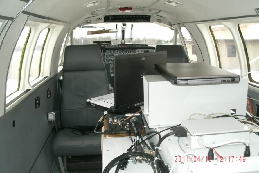
TablesNone
|
|
|
Amphibex Dredging
|
Sediment
|
Removal
|
3+ hours
|
Shoreline
|
This method functions very similarly to the excavator-mounted submersible pump. The Amphibex® has an excavator arm that is mounted to the bow of the boat.
Overview This method functions very similarly to the excavator-mounted submersible pump. The Amphibex® has an excavator arm that is mounted to the bow of the boat. - Conveyance lines are utilized to pump the dredged material to a dredge pad.
- In-situ submerged oil and oiled sediments are pumped into geotextile tubes for dewatering.
- A dredge pad is utilized to contain water and oil that bleeds from the geotextile tubes.
- Oil and water is collected and treated from a sump on the dredge pad.
- A viable option in areas that meet one or more of the following conditions:
- Large enough land area for a dredge pad
- Soft bottom areas
Benefits - Reduced Hand Work
- Proven effectiveness
Limitations - Large land area required for dredge pad
- Ability to access
Figures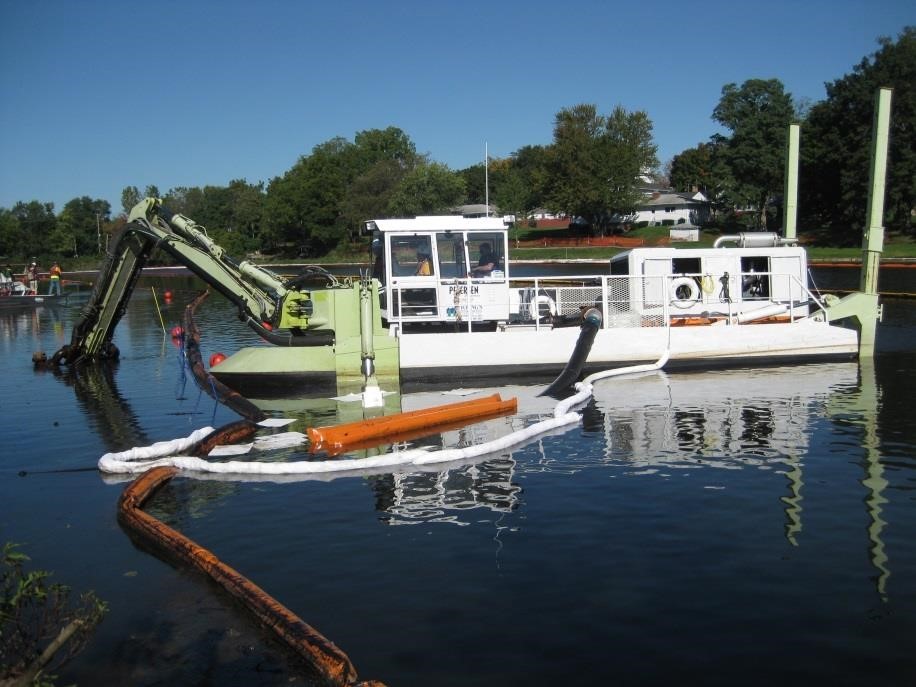
Tables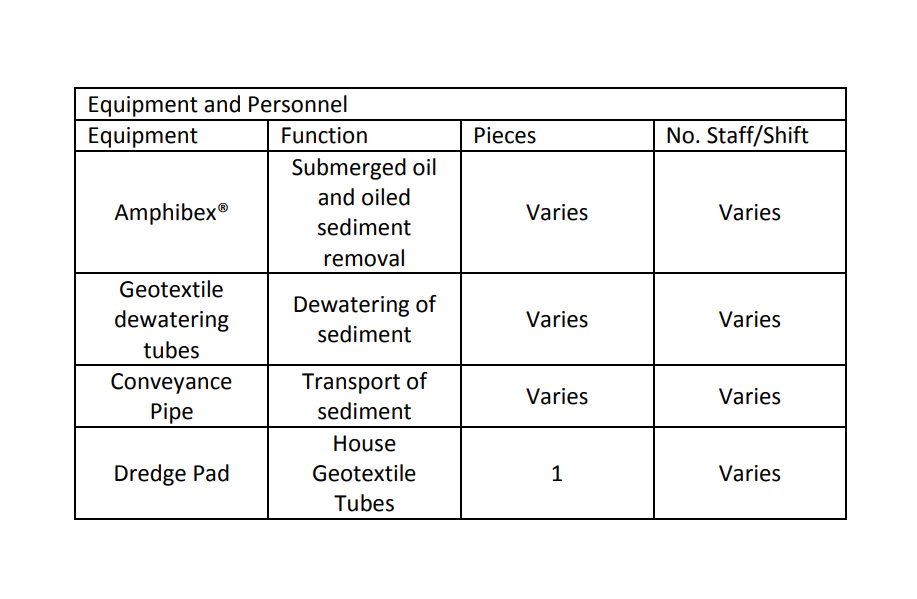
|
|
|
Calculating Proper Deployment of Boom
|
Surface Water
|
Containment
|
0.5-1 hour
|
Open Water (shallow), Shoreline, Culvert
|
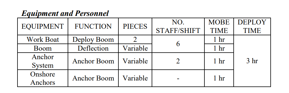
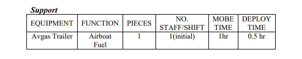
Entrainment refers to the loss of oil from containment when it is pulled under a boom by the water passage below. This typically occurs when boom is deployed at too high an angle.
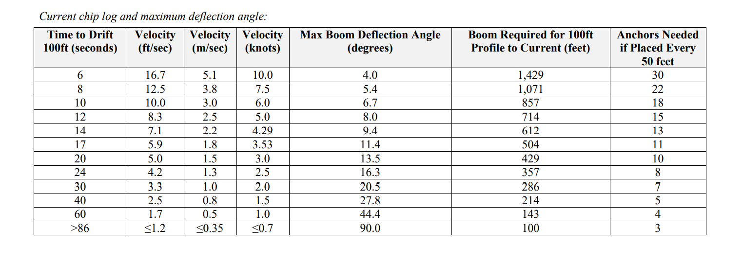
Maximum boom deployment angles to prevent entrainment Entrainment refers to the loss of oil from containment when it is pulled under a boom by the water passage below. This typically occurs when boom is deployed at too high an angle. An accurate determination of current direction and velocity is important in order to select the proper tactic and deploy the equipment correctly. The following tables should be used to determine the appropriate angle at which to set boom. The additional forces exerted on a boom caused by the mooring line angle are often neglected, but they become very large at shallow angles. A boom in a slack “U” configuration has mooring lines parallel with the current or at 0 degrees. The total tension load on each mooring line is simply the drag force on the boom divided by two. As the orientation of the boom mooring line relative to the current approaches 90 degrees, the tension on each mooring line increases dramatically. Tension in the table below is calculated for a 6-inch draft boom with a 100-foot projected sweep width (boom profile) to the current. To measure the speed of the current, time how many seconds it takes for debris to float between two markers 100 feet apart. The following table provides an estimate of the length of boom required for deflecting oil at a specified angle for a 100-foot profile (perpendicular width) to the current. It also provides an estimate of the number of anchors or shoreline tiebacks needed for that length of boom. Figures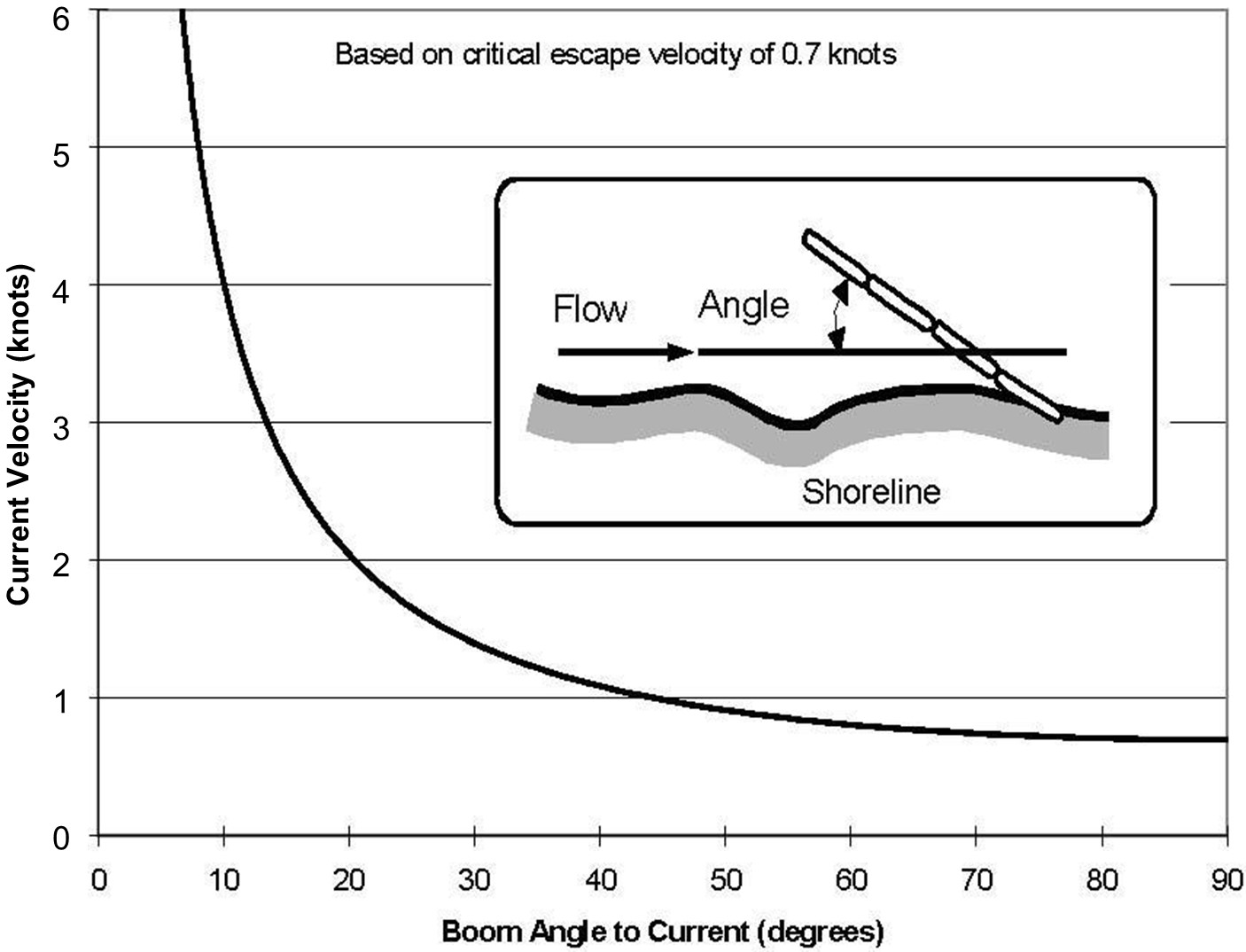
Tables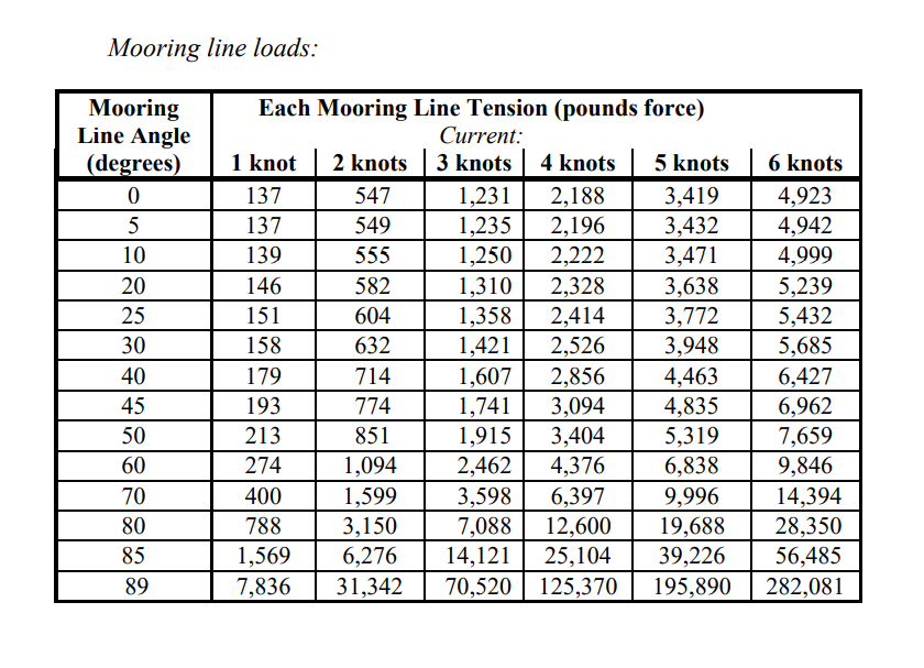
|
|
|
Collection by Chain Drag: Large Equipment
|
Surface Water
|
Collection
|
3+ hours
|
|
The chain drag is an oil recovery tool for submerged environments with minimal debris (fallen trees or submerged stumps). The chain drag apparatus described here is too large for manual deployment.
|
|
|
Collection by Chain Drag: Manual
|
Surface Water
|
Collection
|
3+ hours
|
Open Water (shallow), River/Stream
|
The chain drag is an oil recovery tool for use in submerged environments with minimal debris (fallen trees or submerged stumps).
Overview The chain drag is an oil recovery tool for use in submerged environments with minimal debris (fallen trees or submerged stumps). - The chain drag apparatus consists of a 5-foot long, 2-inch diameter round metal spreader bar with ¼–inch grade 8 metal chains attached at approximately 6-inch centers. A second spreader bar of the same size is attached to the chains to minimize tangling
- The chain drag is pulled either by a shore mounted system or by a boat following a grid layout to ensure complete coverage of the area
- Oil liberated from the sediment is collected by booms and pom pom snares
- The chain drag is an option in areas that meet one or more of the following conditions:
- Open water areas with little to minimal vegetation
- Areas where oil trapped in sediments is the removal target
- Hard or soft bottom areas,>/li>
Benefits - The unit is relatively mobile and can access hard-to- reach areas
- Can be adapted to change depth of sediment agitation
- Prototype was relatively light and maneuverable
Limitations - Larger units may become more difficult to handle and maneuver
- Not usable in areas with considerable submerged debris (rocks, fallen trees or submerged stumps)
- Not intended for use during weather that could interfere with floating oil removal such as rainfall
- The chain drag releases residual oil from sediment using agitation, but it may be ineffective at recovering sinking oils and may actually serve to facilitate downstream transport and likely dispersion.
Figures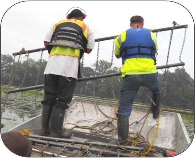 Tables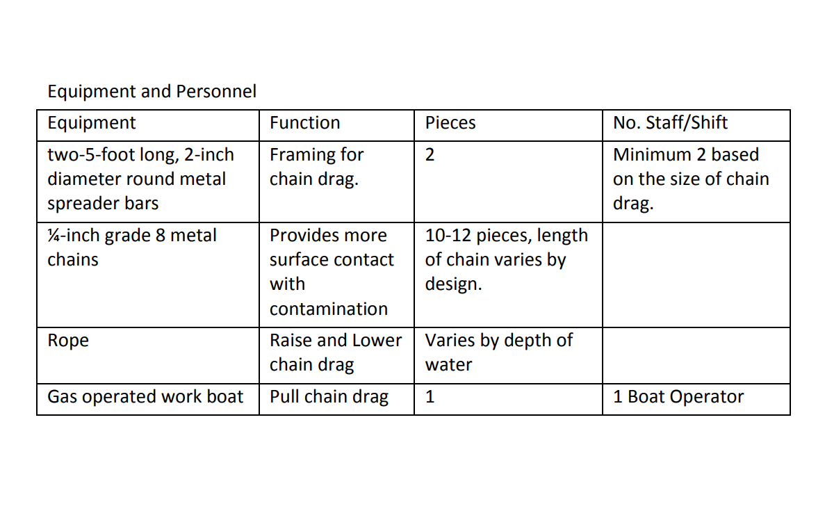
|
|
|
Collection with sorbents
|
Surface Water
|
Collection
|
0-2 hours
|
Shoreline
|
Sorbents can be deployed to serve as a protective agent, a cleanup agent, or both. The sorbent materials such as rolls, pads or snares are placed in the shore zone to collect oil as it comes ashore (protection) or in the oiled area after it has been stranded (cleanup).
Sorbents can be deployed to serve as a protective agent, a cleanup agent, or both. The sorbent materials such as rolls, pads or snares are placed in the shore zone to collect oil as it comes ashore (protection) or in the oiled area after it has been stranded (cleanup). If the spill is at the shoreline, sorbent boom can be deployed and backed up with conventional containment boom as necessary to keep the oil from drifting away. Deployment Considerations and Limitations - Use of sorbents should be minimized because of disposal problem
- Sorbent wringers can be used to extend the life of sorbents
- Do not use pom-poms in conjunction with pumping
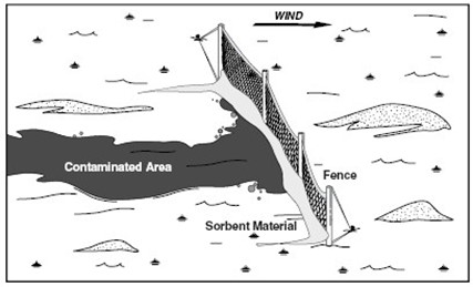
- Sorbents work well on fresh crude, light refined oils, and thick sheens, but are only partially effective on solidified or weathered oil, highly viscous oil, very thin sheens or emulsified oil. Sorbent products are ineffective unless all layers become saturated when in contact with spilled product. Use sorbent boom when overland flow is minor, and terrain has low slope or is wetland.
- Sections of sorbent boom can be placed at the water level and secured with fence posts every 10 feet to catch any oil that may be going back out into the water.
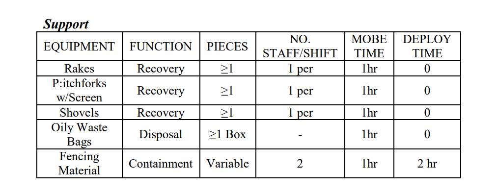
Equipment and Personnel - Personnel requirements depend on the nature and area of oil contamination. Personnel typically work in pairs for sorbent deployment and recovery. Additional personnel are required for loaders, dump trucks, vessel, etc.
Figures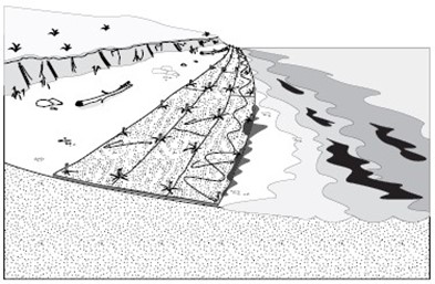
Tables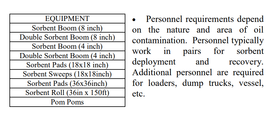
|
|
|
Collection by Direct Suction
|
Other
|
Disposal
|
0-1 hour
|
Road
|
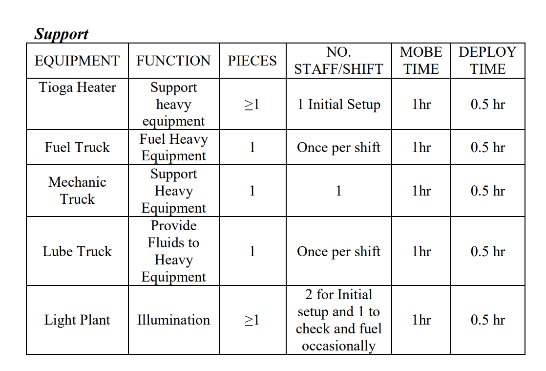
For spills off pad or road, a vacuum truck can effectively reach out 200 feet. If the oil is pooled on water, a Manta Ray skimmer head is attached to the hose extending from the vacuum truck.
For spills off pad or road, a vacuum truck can effectively reach out 200 feet. If the oil is pooled on water, a Manta Ray skimmer head is attached to the hose extending from the vacuum truck. The hose or skimmer head is placed in the pooled oil for recovery. SRT staff man the hose or skimmer head and move it to other pooled areas as necessary. A Super Sucker can also be used for direct suction. DOP pumps or 4-inch trash pumps can also be used for this task since they can move oil more than 200 feet, and could either pump the pooled oil into vacuum trucks on a pad/road, into holding tanks, or into the slop oil tank at a nearby production facility. Free oil can be recovered from any pooled area including natural depressions, barriers, constructed trenches, or containment dikes. Deployment Considerations and Limitations - Vacuum trucks provide efficient spill recovery, unless vehicle access is prohibited or not possible, the spill is unpumpable (highly viscous, cold or weathered), the spill is in a thin layer, or debris will clog the recovery line.
- Identify the disposal facility to be used before calling out a vacuum truck
- Viscous liquids accessible within 200 ft by a vacuum truck are recovered with direct suction of that vacuum truck. Pooled areas could be in natural depressions or in constructed trenches.
- Vacuum trucks can access pooled diesel up to 400 ft away from the truck
- Use of Manta Ray skimmers with vacuum trucks decreases recovery capacity.
- Super Suckers are available to remove liquids with solids that vacuum trucks cannot handle.
- With a trash pump, the suction head must be completely submerged.
- Since a DOP pump is submersible, oil must be deep enough for effective pumping.
- The amount of oil will be estimated based on gauging by appropriate means (e.g., Coliwasa tube). Emulsion samples will be collected and analyzed for oil content.
Figures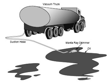
Tables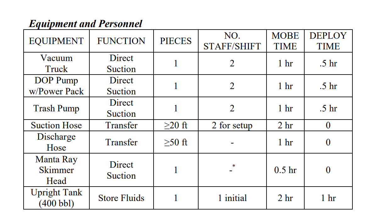
|
|
|
Collection Under Ice
|
Other
|
Collection
|
0.5-1 hour
|
Ice
|
A sump is cut in the ice around a hole augered through the ice to pockets of oil under the ice or encapsulated in the ice.
A sump is cut in the ice around a hole augered through the ice to pockets of oil under the ice or encapsulated in the ice. The oil is pumped directly from the sump to temporary storage containers. A heated shelter can be erected over the sump. Another option involves deploying rope mop through holes in the ice to recover oil trapped in under-ice depressions. Two holes are drilled in the ice using ice augers or chainsaws, and the rope mop is strung under the ice between the holes. Deployment Considerations and Limitations - Heat inside the shelter will make the rope mop and pump more effective
- Disposal of construction material should be taken into account before using this tactic
- Check the thickness for safe bearing capacity before working on ice. The ice must be sufficiently strong to support personnel and heavy equipment. Also, ensure ice can withstand extra load of oil and snow on the surface without either breaking the ice or forcing oil to migrate through existing cracks. Extreme care must be taken when positioning or operating any heavy equipment close to trenches or slots in the ice. Stresses in the ice for a given load can double under these situations. Ensure that oil that accumulates in an ice trench is continually removed. If allowed to build up to a thick layer, some oil may escape the ice slot.
Figures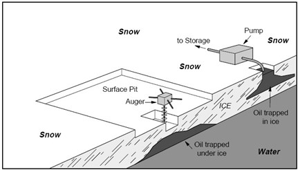
Tables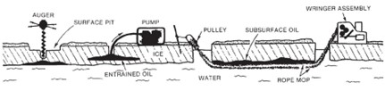
|
|
|
Collection with Portable Skimmers and Pumps
|
Surface Water
|
Removal,Recovery
|
0.5-1 hour
|
Shoreline, Culvert,Road
|
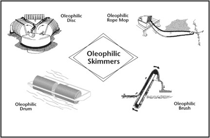
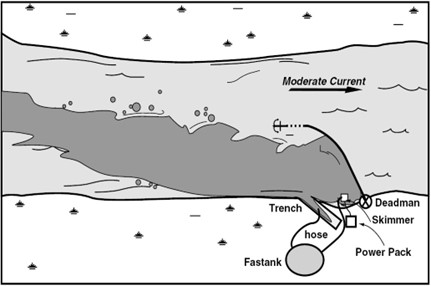
Portable skimmers are easily mobilized, transported, and deployed and can be used in most spill situations for recovery. They can be used to recover oil from containment areas such as the apex of a diversion boom or natural or artificial deadarms.
Portable skimmers are easily mobilized, transported, and deployed and can be used in most spill situations for recovery. They can be used to recover oil from containment areas such as the apex of a diversion boom or natural or artificial deadarms. The typical portable skimming system includes: - Skimmer, pump, or skimmer/pump (with fuel) with power pack
- Hose (suction and discharge with fittings)
- Storage container (tank truck, storage bladder, barrels, Fastank, etc.)
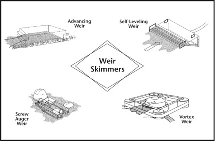
Portable skimmers can be deployed on land or from small boats to recover oil contained on water. A weir skimmer has a “lip” or weir at its intake over which liquids flow into the skimmer pump. The user can adjust the working depth of the weir. Weir skimmers will pick up any product on water, including emulsified and weathered product; however, they recover more water than oil in thin oil layers. (Avoid using a centrifugal pump since emulsification will occur; use a diaphragm pump instead.) Oil adheres to an oleophilic skimmer, while water is repelled. These skimmers include rotating disks, rotating drums, or endless belts (including rope mop). Brush and rope mop skimmers can be effective in any oil thickness, while disk and drum skimmers require fresh oil. (Any pump can be used as long as the pump rate can be adjusted so as not to exceed the recovery rate of the skimmer). Deployment Considerations and Limitations - Portable skimmers are initially used to pick up concentrationsof oil, then are used in containment areas. The skimmers can be land-based or deployed from boats, and require power packs (a jon boat can be used for the power pack). When requesting a skimmer, always ask for the total skimming system
- The only differences in equipment or techniques for road access or no road access are logistical in nature.
- Position the skimmer or pump with suction hose in area of heaviest spill concentration. Make sure intake end of hose is fitted with a screen. Use a diaphragm pump (not a centrifugal pump) with a weir skimmer.
Equipment and Personnel - Typically, portable skimmers require 2 persons for setup and 1 or 2 people to operate.
Support - Fold-A-Tank, bladders, Fastanks, Rolligon with tank, mini- barge possible.
Figures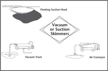
TablesNone
|
|
|
Containment Booming in Open Water
|
Surface Water
|
Containment
|
0.5-1 hour
|
Open Water (shallow), Shoreline, Culvert
|
Exclusion and deflection tactics (also outlined in this appendix) are often used as part of the containment and collection strategies.
Exclusion and deflection tactics (also outlined in this appendix) are often used as part of the containment and collection strategies. Once contained, there are a variety of recovery tactics that can then be used to recover the oil. The type of containment tactic depends highly on the location of the spill, whether in water or on land, and the environmental conditions, whether there is snow or ice present. In larger areas of open water two boats, as shown in the illustration, can tow containment booms of up to 1000 feet. This method can be used for temporary containment and/or transport of oil. Figures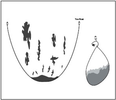
Tables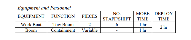
|
|
|
Containment with Gate Weir
|
Surface Water
|
Containment
|
0.5-3 hours
|
Shoreline
|
The Fairchild gate weir provides a closable opening for an existing storage trench or deadarm along a river bank.
The Fairchild gate weir provides a closable opening for an existing storage trench or deadarm along a river bank. Oil moving on the river is deflected so that it enters the recovery weir into the storage area, and the liquid flow can be controlled as necessary. A 3- or 4-inch trash pump is used to decant fluids back upstream into the boomed area. This will allow for greater storage capacity in the trench area. Deployment Considerations and Limitations - Use an existing trench or deadarm. If necessary, dig a new one or modify an existing one
- Disposal of construction material should be taken into account before using this tactic
- Do not excavate where excavation will cause more damage than the spill.
- The amount of oil will be estimated based on gauging by appropriate means. Emulsion samples will be collected and analyzed for oil content.
Figures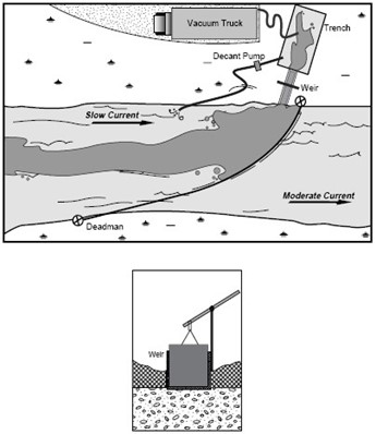
Tables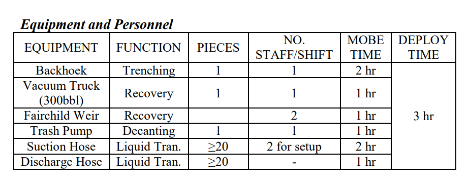
|
|
|
Flooding and Flushing the Shoreline
|
Soil
|
Cleaning
|
0.5-1 hour
|
Shoreline
|
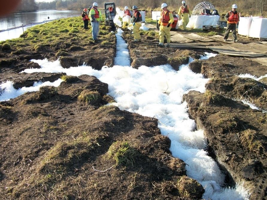
Physical removal involves a variety of washing or flushing tactics to move oil from the shore zone to a location for collection and removal.
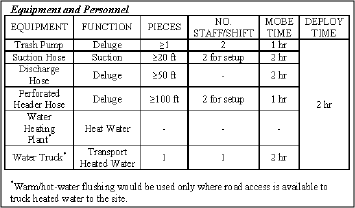
Physical removal involves a variety of washing or flushing tactics to move oil from the shore zone to a location for collection and removal. The variables that distinguish each tactic are pressure and temperature. For all these tactics, booms or other methods of trapping and containment are used to collect the oil for removal. Flooding (“Deluge”) A high-volume (50 to 250 gpm), low-pressure supply of water at ambient temperature is pumped using large-diameter (3 to 6-inch) pipe and/or hose (“header”) to the upper section of the oiled area. Water can be pumped either directly from a hose without a nozzle, or the pipe or hose can be perforated (0.1 to 0.2-inch holes) at intervals and placed along the shoreline parallel to the water line. Output pressures are less than 20 psi. The high volume of water floods the surface area (in the case of impermeable man-made shorelines) or the beach sediments. Mobile or non-sticky oil is transported with the water as it flows downslope. Flooding can be used in combination with trenches or sumps and vacuum systems to float and collect oil for recovery. Low-Pressure, Ambient-Water Flushing Hand-operated or remote-controlled hoses use ambient temperature water to flush, wash, and herd oil to a collection point for removal. Output pressures are controlled, usually by a nozzle, and are low (less than 50 psi). The tactic can be used with flooding to prevent redeposition of the oil. Low-Pressure, Warm/Hot-Water Flushing Hand-operated or remote-controlled hoses use heated (80 to 212 F) water to flush, wash and herd oil to a collection point. This tactic is used primarily to dislodge and flush oil that cannot be washed using low-pressure, ambient-temperature water. Output pressures are controlled, usually by a nozzle, and are low (less than 50 psi). This tactic can be used with flooding to prevent redeposition of the oil. High-Pressure, Ambient-Water Flushing Hand-operated or remote-controlled hoses use ambient temperature water jets to flush, wash, and herd oil to a collection point. The higher water pressures dislodge and flush oil that cannot be washed or mobilized using lower pressure, ambient temperature water. Output pressures are controlled and are in the range of 100 psi or greater. On sloping outcrops or structures this technique can be used with flooding to prevent redeposition of the oil. High-Pressure, Warm/Hot-Water Flushing Hand-operated or remote-controlled hoses use high-pressure, heated (80 to 212 F) seawater to flush, wash and herd oil to a collection point. Output pressures may be fixed or controlled by a nozzle and are in the range of 100 psi or greater. The higher pressure and warm water dislodge and flush oil that cannot be washed by lower pressure and temperature water. On sloping structures, this technique can be used with flooding or low- pressure flushing to prevent redeposition of the oil. Deployment Considerations and Limitations - Unified Command approval is required for any shoreline cleanup tactic
- Flooding is effective on most shoreline types, but it may have limited application only on sand or mud flats and on steep man-made solid structures. Generally, flooding is not a very intrusive technique.
- Low-pressure, ambient water flushing is effective on most impermeable shoreline types and on some permeable shores or marshes. It may have limited application only on sand beaches, sand-gravel beaches, or sand flats and is probably not appropriate on mud flats. Generally, this is not an intrusive technique and leaves most organisms in place.
- Low-pressure, warm/hot water flushing is effective on most impermeable shoreline types, but may have limited application only on sand beaches, sand-gravel beaches, and sand flats and is probably not appropriate on mud flats. Generally, this is not a highly intrusive technique if used carefully in conjunction with high-volume flooding, which minimizes the potential adverse effects o shoreline organisms of using heated water.
- The effectiveness of flooding and lo-pressure flushing decreases as oil viscosity increases and as depth of penetration increases on cobble beaches.
- High-pressure, ambient-water flushing has limited application only for oiled bedrock or solid man-made shorelines. High- pressure water can dislodge attached organisms and may damage others.
- High-pressure, warm/hot-water flushing usually has only limited application for solid man-made structures. The heated water or the pressures may dislodge attached organisms or damage others.
Figures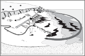
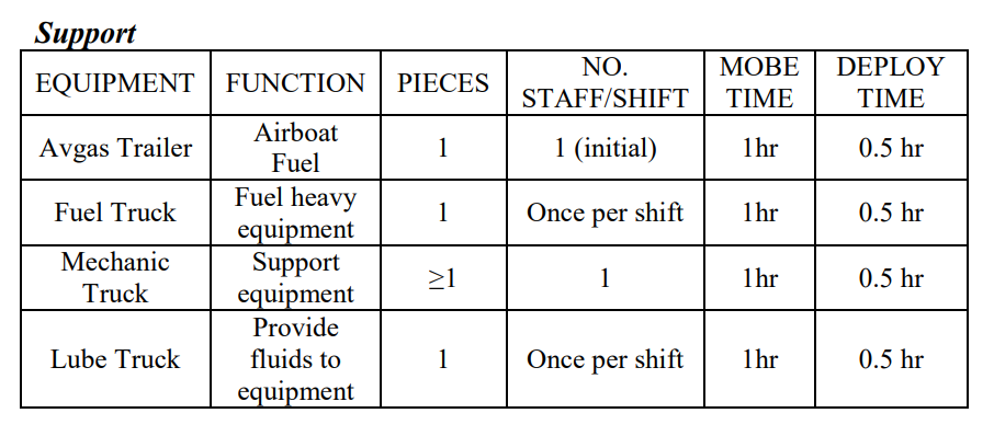
TablesEquipment and Personnel
|
|
|
Collection In Ice with Trenches and Sumps
|
Surface Water
|
Collection
|
0.5-2 hours
|
Ice
|
Partial trenches or through -ice slots can be dug in the ice surface with a Ditch Witch to encourage oil flow to a collection point.
Various techniques that are used on land can also be used on solid ice. (1) Partial trenches or through-ice slots can be dug in the ice surface with a Ditch Witch to encourage oil flow to a collection point. (2) The skirt of a containment boom can be set in a shallow trench to provide additional containment. (3) Another approach is to insert a plywood or metal barrier in a slot so that the barrier freezes in place. This tactic can be used to divert under-ice oil to a recovery point. For smaller volumes of oil on ice, small snow berms can be created to contain the oil, but only where ice is thick enough and/or grounded to prevent cracking, pooling, and forced migration of oil below the ice. Deployment Considerations and Limitations - Check ice thickness for safe bearing capacity before working on ice. The ice must be sufficiently strong to support personnel and heavy equipment. Also, ensure ice can withstand extra load of oil and ice on the surface without either breaking the ice or forcing oil to migrate through existing cracks. Extreme care must be taken when positioning or operating any heavy equipment close to trenches or slots in the ice. Stresses in the ice for a given load can double under these situations. Ensure that oil that accumulates in an ice trench is continually removed. If allowed to build up to a thick layer, some oil may escape the ice slot.
Figuresp>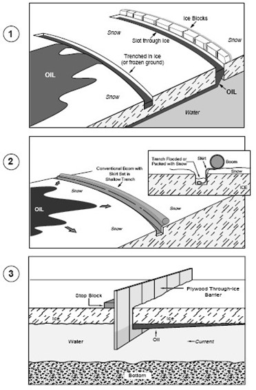 Tables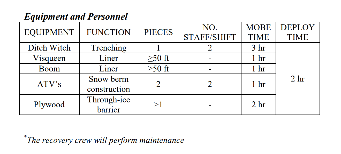
|
|
|
Land Barriers
|
Soil
|
Containment,Exclusion
|
0-2 hours
|
Land
|
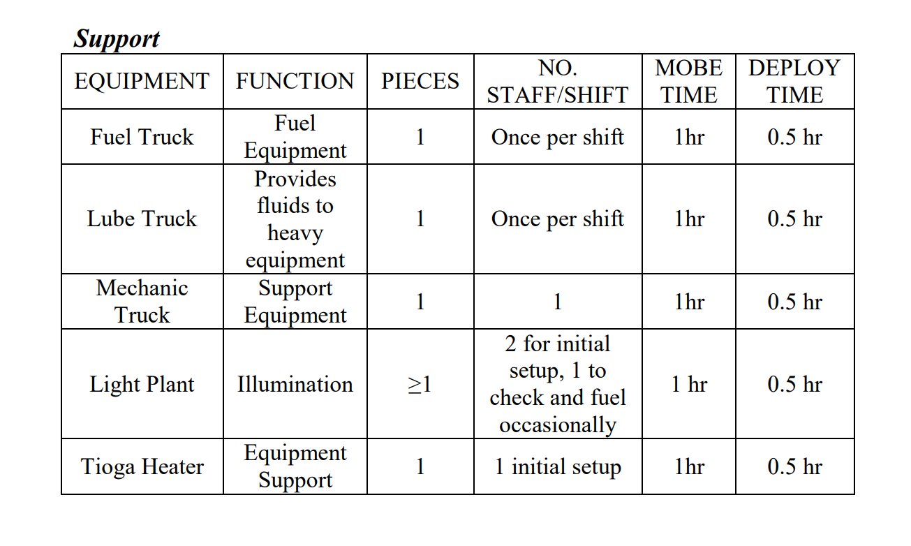
A containment berm can be constructed of available materials such as earth, gravel, or snow. Use earth-moving equipment or manual labor to construct the berm.
A containment berm can be constructed of available materials such as earth, gravel, or snow. Use earth-moving equipment or manual labor to construct the berm. Form the materials into a horseshoe shape ahead of the flow of oil. Use plastic sheeting to line the walls of a soil berm to prevent oil penetration. Because of the sorbent quality of snow, it makes an excellent berm for both containment and recovery. A snow berm can be strengthened by spraying it with a fine water mist that forms an ice layer on top of the snow. Sandbags filled with sand or other heavy material also make excellent containment barriers. Sorbent boom can be used when overland flows are relatively minor or in wetlands. The sorbent boom should be staked in place with stakes approximately 5 feet apart. These barriers can serve to: - Contain and stabilize a contaminated area
- Contain or divert oil on water or oil that has potential to migrate
- Create cells for recovery
- Block natural depressions to act as containment areas for recovery
An excavated trench or a berm can also be used to intercept the flow of a spill or divert the flow around a sensitive area. Dig the trench at right angles to the flow of the spill. The trench should be angled slightly downslope to avoid excessive pooling in the trench. Place excavated material on the downhill side of the trench. In areas with a low water table, line the sides and bottom of the trench with plastic sheeting or similar impermeable materials. If the groundwater table is high, line the downhill side of the trench. The trench can be flooded with water to inhibit spill penetration into sediments and to stimulate flow toward the recovery device in the trench or pit. Deployment Considerations and Limitations - Disposal of construction material should be taken into account before using this tactic
- This tactic is appropriate for use with low flow and shallow water areas
- Do not excavate where excavation will cause more damage than the spill. The bobcat trimmer is the last option for trenching. A permit may be needed from the landowner.
- When working with equipment around or near flow lines, a spotter must be added to each front-end loader.
- A civil work permit from the operator is required for all work on owner-company pads.
Figures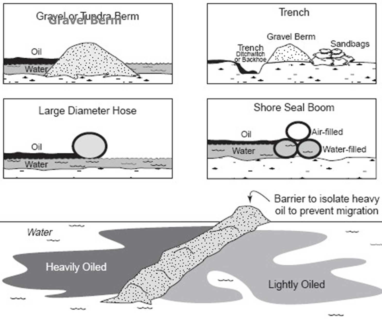
TablesEquipment and Personnel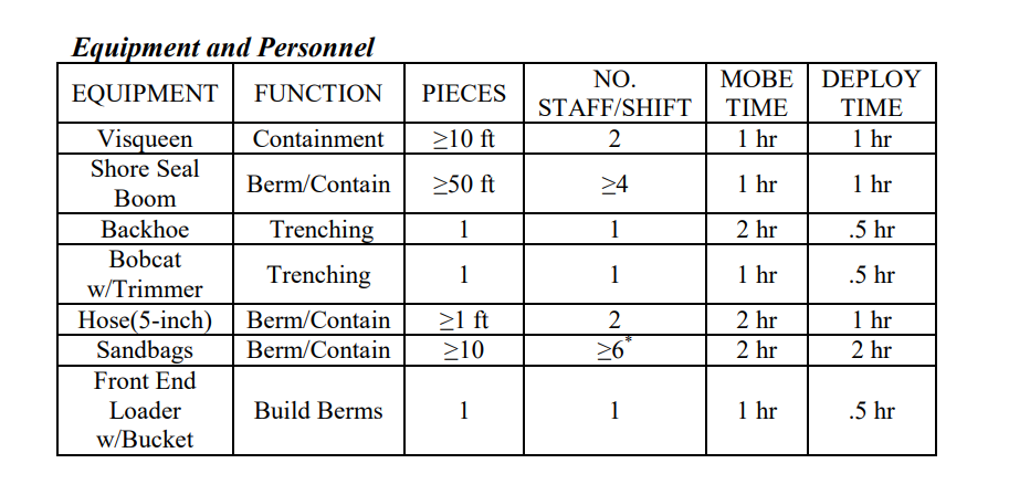
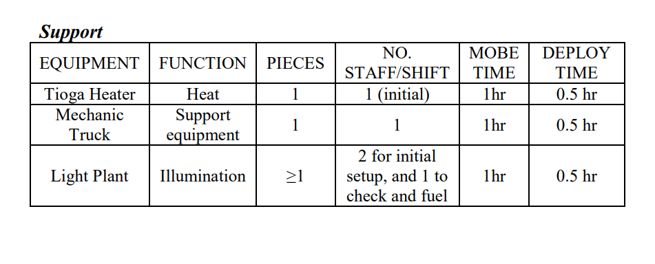
Support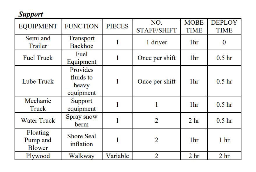
|
|
|
Underflow Dams
|
Surface Water
|
Containment
|
0.5-2 hours
|
River/Stream
|
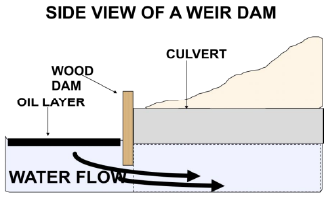
An underflow dam can be used when there is too much water flow to allow for a complete blockage of a drainage channel.
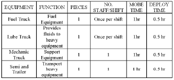
An underflow dam can be used when there is too much water flow to allow for a complete blockage of a drainage channel. The dam is built of earth, gravel, or other barriers such as sandbags or plywood sheets. Wherever possible, line the upstream side of the dam with plastic sheeting to prevent erosion and penetration of oil into the dam material. An underflow dam can contain free floating oil and allow uncontaminated water to pass through inclined pipes in the dam. The capacity of the pipe(s) should exceed the stream flow rate. It may be necessary to use pumps to control or increase flow through the pipes. Pipes must be placed low on the upstream side of the dam, with the elevated end on the downstream side. Make sure that the upstream end of the pipe is submerged and below the oil/water interface. The height of the elevated downstream end of the pipe will determine the water level behind the dam. Alternative methods include adding a valve on the downstream end, or a “T” on the upstream end of a level pipe. The “T” opening not only allows uncontaminated water to flow through the pipe, as with the standard design, but also gives access to responders to remove debris. Weir dams are used to block the flow of oil through a culvert while letting uncontaminated water pass. A plywood or similar barrier is fixed to the upstream opening of the culvert. The lower edge of the plywood is below the oil/water interface and above the bottom of the culvert. Adjust size of the opening depending on flow rate. Deployment Considerations and Limitations - Sufficient pipe must be used to handle maximum stream flow. The number, size, length, and position of pipes vary with volume of water, velocity, width of stream, and other factors. The pipes can be plastic or steel, plain or corrugated.
- Check dams regularly for leakage and integrity. Replace eroded material as needed. Monitor oil/water interface. Changes in stream flow may require adjustment of pipes or dam height.
- The outlet of the pipe(s) must not be higher than the dam or adjacent banks, or water will back up and crest over the dam or flood past on the banks.
- Insufficient drainage through pipes will also lead to cresting. Pipes that are too level or allow excessive drainage will drop the water level enough to allow oil to pass through the dam.
- If the dam material is unlined and not wide enough or compact enough, water will saturate the dam, causing it to fail catastrophically.
- Seal the edges of a weir dam with hard-packed earth to prevent oil from seeping between plywood and culvert. Anchor the plywood in place using stakes, sandbags, or rock.
Figures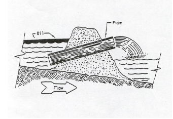 class="tactics-col-2" alt="diagram of an underflow dam"/> class="tactics-col-2" alt="diagram of an underflow dam"/>
 Tables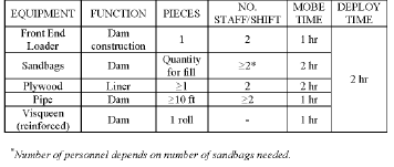
|
|
|
Diversion: Booming in a Stream
|
Surface Water
|
Diversion
|
0.5-3 hours
|
River/Stream
|
Boom within a fast moving stream to remove oil from the fastest water and divert it to slower water.
The objective of stream booming is to remove oil from the fastest water and divert it to slower water. A stream can be boomed by deploying the boom either upstream or downstream. In either case, the boom is first set out on the stream bank. Before the boom is deployed, rig anchor points on the boom. The boom is attached to a shore anchor, and then the boom is either towed upstream to a midstream anchor point, or the boom is allowed to drift down- stream with the current. Once the boom is set, intermediate anchors are set as needed to ensure that the boom maintains the proper configuration (remembering that the current perpendicular to the boom should not exceed ¾ knot). Examples of deployment configurations follow. Diversionary (single boom): A boom is deployed from one bank at an angle to the current and anchored midstream or on the opposite bank for diverting the oil to an eddy or other quiet-water collection point on the shoreline. Alternatively, a single long boom can be used in a multichannel stream to divert oil so that it stays in one channel. Diversionary (cascade): Several booms are deployed in a cascade fashion when a single boom can’t be used because of a fast current or because it’s necessary to leave openings for boats to get through. This configuration can be used in strong currents where it is impossible or difficult to deploy one long boom. Shorter sections of boom used in a cascade deployment are easier to handle in fast water. However, more equipment is needed than when a single boom is used. Deployment Considerations and Limitations - 8x6 Delta boom is most commonly used for this tactic
- Since the speed of the current perpendicular to the boom must be maintained at ¾ kt or less, the length of boom needed to stretch across a stream depends on the current. For a stream 100ft across with a 1kt current, a boom approximately 140 ft long is needed. If the current is 2kt, the same stream would require 320 ft of boom. The speed of the current is not equal across the stream; the fastest water is with the deepest water. Oil moving in a stream will be entrained in the fastest water.
- The shortest length of boom available is 50 ft.
- Readjust angles and widths between boom sections as current and wind change. Constantly monitor nearshore boom systems to prevent escape of oil.
Figures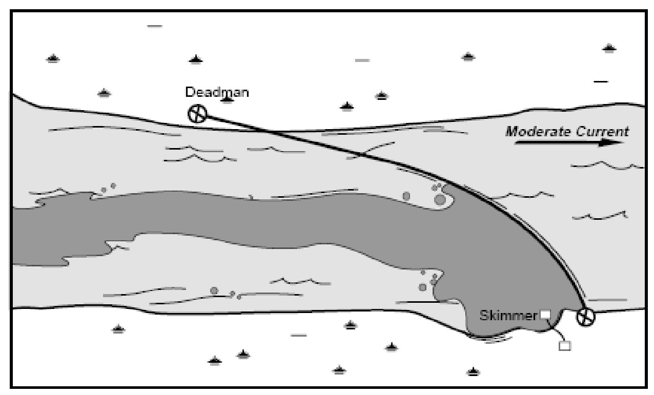
TablesEquipment and Personnel
Support Equipment
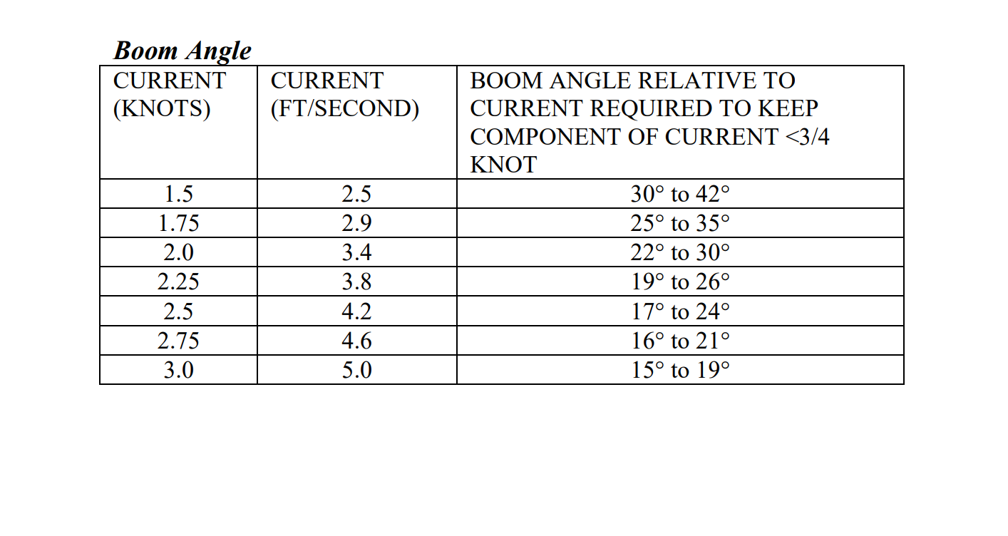
Boom Angle
|
|
|
Diversion: Booming in Open Water
|
Surface Water
|
Containment
|
0.5-3 hours
|
Open Water (shallow), Shoreline, Culvert
|
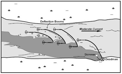
Deflection booming is often used where the water current is greater than 1 knot or where exclusion boom does not protect the shoreline. Deflection booming diverts oil to locations that are less sensitive or more suitable for recovery.
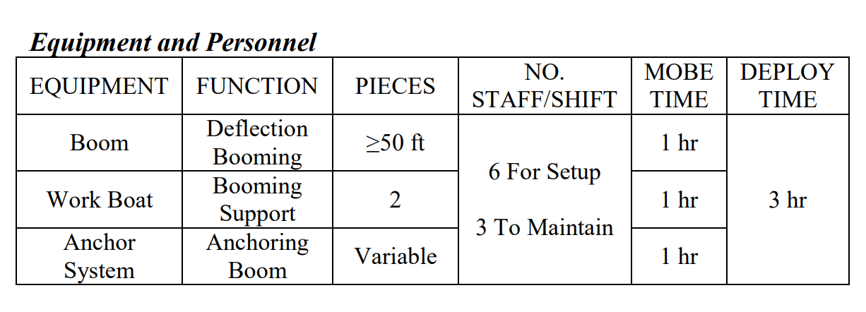
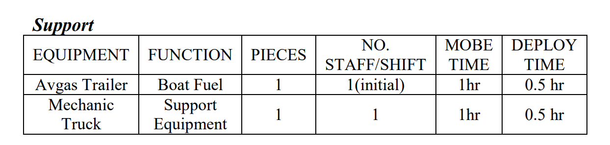
Deflection booming is often used where the water current is greater than 1 knot or where exclusion boom does not protect the shoreline. Deflection booming diverts oil to locations that are less sensitive or more suitable for recovery. Boom is anchored at one end at the shoreline, while the free end is held at an angle by an anchor system. Deflection boom is deployed at an angle to the current to reduce and divert surface flow. This allows the oil to move along the boom and eliminates vortexes and entrainment. Anchoring is usually placed every 50 feet depending on the current. Anchoring distance will vary depending on current. Cascading deflection boom involves two or more lengths of boom ranging from 100 feet to 500 feet placed in a cascading formation in the water. The lead boom deflects the slick, and subsequent booms placed downstream of the lead boom continue the deflection process until the slick is directed to the desired area. Deployment Considerations and Limitations - The optimum angle of boom deployment depends on the current speed and the length and type of boom. The angle is smaller in strong currents than in weak currents and decreases as boom length increases. The more stable the boom is, the larger the optimum deployment angle is for a given current speed. Because deflection booms significantly reduce surface current, successive booms are deployed at increasingly larger angles.
- Don’t assume 100% containment with one boom system
- Readjust angles and widths between boom sections as current and wind change. Constantly monitor nearshore boom systems to prevent escape of oil
Figures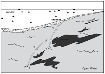
TablesEquipment and Personnel
Support Equipment
|
|
|
Excavator-Mounted Submersible Pump
|
Sediment
|
Removal,Recovery
|
3+ hours
|
Shoreline
|
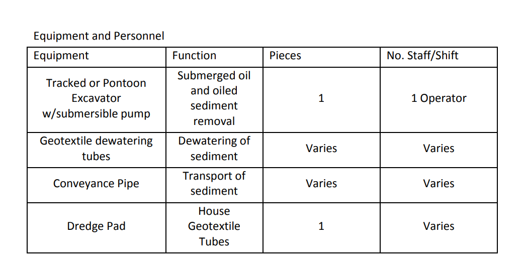
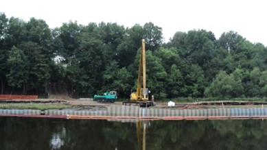
The submersible pump mounted to the stick of the excavator and used to remove submerged oil and oil-contaminated sediments, paired with a shore-based material handling station.
Overview The submersible pump mounted to the stick of the excavator and used to remove submerged oil and oil-contaminated sediments, paired with a shore-based material handling station. The submersible pump must be able to handle up to 70% solids. The pump can be mounted to either a tracked excavator that remains on the banks of the waterbody, or a pontoon excavator that can enter the waterbody. - Conveyance lines are utilized to pump the dredged material to a dredge pad.
- In-situ submerged oil and oiled sediments are pumped into geotextile tubes for dewatering.
- A dredge pad is utilized to contain water and oil that bleeds from the geotextile tubes.
- Oil and water is collected and treated from a sump on the dredge pad.
- A viable option in areas that meet one or more of the following conditions:
- Large enough area on land for a dredge pad
- Areas where submerged oil is the removal target
- Soft bottom areas
Benefits - Reduced Hand Work
- Proven effectiveness
Limitations - Large land area required for dredge pad
- Ability to access
Figures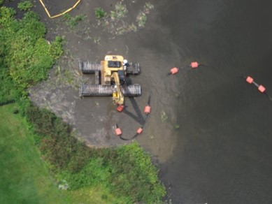
TablesEquipment and Personnel
|
|
|
Exclusion: Booming at a Culvert
|
Other
|
Exclusion
|
0-3 hours
|
Culvert
|
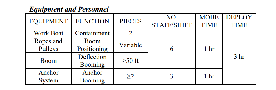
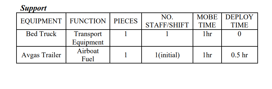
In many spill response situations it may be necessary to prevent the oil from flowing into a culvert. Blocking the culvert introduces the risk of washing out the feature that is above the culvert, in most cases a road.
In many spill response situations it may be necessary to prevent the oil from flowing into a culvert. Blocking the culvert introduces the risk of washing out the feature that is above the culvert, in most cases a road. Under these circumstances boom should be deployed in either a multiple chevron or a diversionary deflection configuration. This will deflect the oil from the mouth of the culvert and cause it to collect along the road. Deployment Considerations and Limitations - 8x6 Delta boom is most commonly used for this tactic
- The speed of the current perpendicular to the boom must be maintained at ¾ knot or less to prevent oil loss.
- The number and configuration of booms depend on flow rate and number of collection sites. With any boom system do not assume 100% containment with one system.
- An assortment of skimmers can be used alongside the roadway. When selecting a skimmer, consideration must be given to oil viscosity, available capacity, and volume of oil to be recovered.
Figures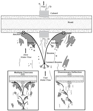
TablesEquipment and Personnel
Support Equipment
|
|
|
Exclusion: Booming in Open Water
|
Surface Water
|
Exclusion
|
0.5-3 hours
|
Open Water (shallow), Shoreline, Culvert
|
Boom is placed across small inlets and creek mouths identified as sensitive areas. Exclusion booming is used where currents are less than 3/4 knot and breaking waves are less than .5 foot in height.
Boom is placed across small inlets and creek mouths identified as sensitive areas. Exclusion booming is used where currents are less than 3/4 knot and breaking waves are less than .5 foot in height. The boom is either (1) anchored from shore to shore across the mouths of streams or (2) at an angle to a shoreline to guide oil past the sensitive area. Crews with work boats deploy and tend boom along the shoreline in marshes and inlets. Deployment Considerations and Limitations - Exclusion booming is effective if the water currents are less than 3/4 kt, breaking waves are less than .5 ft, and water depth is at least twice the boom depth in other than intertidal areas.
- A flexible curtain-type boom reacts more favorably to tidal level fluctuation than a rigid fence-type boom.
- Exclusion booming is most effective across small stream mouths or inlets. Other areas may be more sensitive and require protection, but ability to protect efficiently needs to be considered when determining exclusion bomming areas.
- Don’t assume 100% containment with one boom system
- Readjust angles and widths between boom sections as current and wind change. Constantly monitor nearshore boom systems to prevent escape of oil
Figures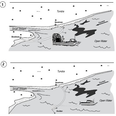
TablesEquipment and Personnel
Support Equipment
|
|
|
Exclusion: Booming on a River
|
Surface Water
|
Exclusion
|
1.5-3 hours
|
River/Stream
|
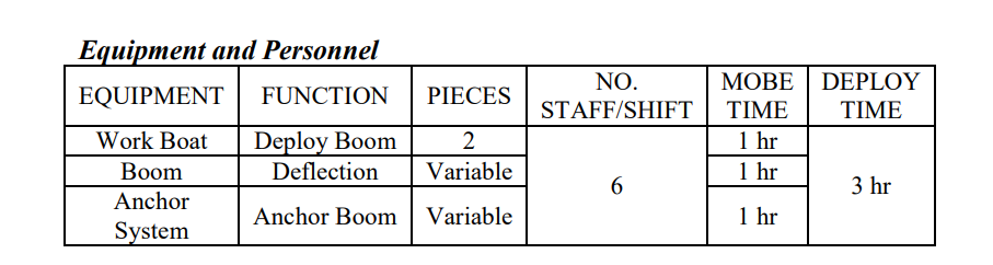
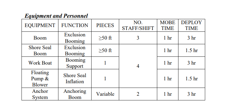
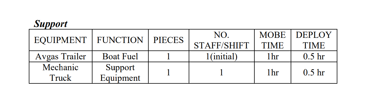
Either conventional boom or a Shore Seal boom can be used to exclude oil from a sensitive area. For example, the Shore Seal boom can be used in shallow water to boom off a back-water, or a conventional boom can be placed across the mouth of a side channel to keep oil out.
Either conventional boom or a Shore Seal boom can be used to exclude oil from a sensitive area. For example, the Shore Seal boom can be used in shallow water to boom off a back-water, or a conventional boom can be placed across the mouth of a side channel to keep oil out. In addition, Shore Seal boom can be connected to conventional boom to protect the shoreline. Deployment Considerations and Limitations - 8x6 Delta boom is most commonly used for this tactic.
- Since the speed of the current perpendicular to the boom must be maintained at ¾ kt or less, the length of boom needed to stretch across a stream depends on the current. For a stream 100ft across with a 1kt current, a boom approximately 140 ft long is needed. If the current is 2kt, the same stream would require 320 ft of boom
- The speed of the current is not equal across the stream; the fastest water is with the deepest water. Oil moving in a stream will be entrained in the fastest water
- Don’t assume 100% containment with one boom system
- Readjust angles and widths between boom sections as current and wind change. Constantly monitor nearshore boom systems to prevent escape of oil
Figures
TablesEquipment and Personnel
Support Equipment
|
|
|
Gabion-type baskets
|
Surface Water
|
Removal,Containment
|
0.5-1 hour
|
Open Water (shallow)
|
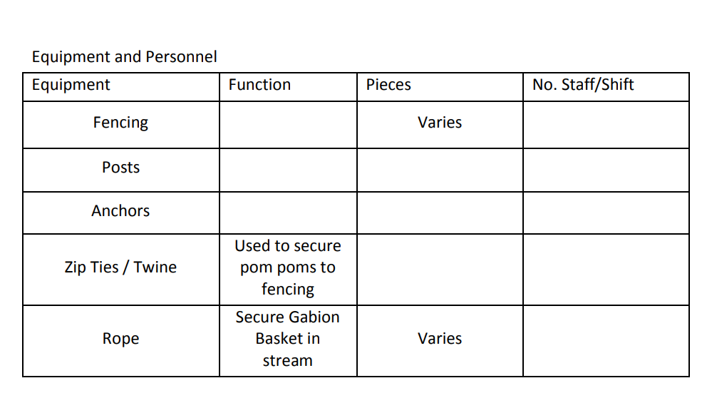
Baskets are constructed using dog kennels and sweep boom and/or pom pom snares, and are then placed in strategic locations to catch released submerged oil.
Overview Baskets are constructed using dog kennels and sweep boom and/or pom pom snares, and are then placed in strategic locations to catch released submerged oil. - Dog Kennels
- Sweep / Pom Pom snares
Benefits - Sturdy apparatuses
- Long-term installation possible
- Collection of suspended oil at varying depths in the water column
- Requires little manual intervention once placed in water
Limitations - Heavy, awkward to place initially and to move once placed
- Replacement of underwater boom difficult, labor- intensive
Figures
TablesEquipment and Personnel
|
|
|
Hand-held Stinger
|
Sediment
|
Containment
|
0.5-1 hour
|
River/Stream
|
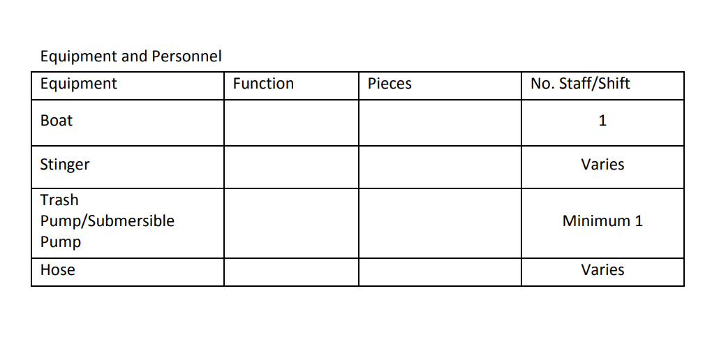
A stinger consists of a hand-held discharge wand connected to a boat�mounted pump, which utilizes river water to ‘inject’ water into sediment, releasing submerged oil.
Overview A stinger consists of a hand-held discharge wand connected to a boat- mounted pump, which utilizes river water to ‘inject’ water into sediment, releasing submerged oil. - The water injecting/flushing device is constructed using an 8-foot- long, 1 ½-inch diameter steel vertical pole with a 45-degree elbow fitting and a short nozzle of 1 ½-inch pipe that has been flattened to create a fan-like water discharge
- Uses high volume/low pressure supplied by a submersible, trash or water pump
- This tool can be modified to include three or four vertical pipes welded together on 6-inch to 8-inch centers with 90-degree (or greater) fittings
- Entire area is flushed using an overlapping sweeping motion to ensure complete coverage of the area
- Sorbent materials are used for the collection and removal of recovered oil
Benefits - The single nozzle is much more forceful than the rotating stingers (see next section)
- Relatively mobile
Limitations - Can only cover a very small area at a time
- Multiple passes through an area are required for complete coverage
- Physically demanding for operator to control its movement
- The recovery of residual oil using sediment agitation may be ineffective at recovering sinking oils, and may actually serve to facilitate downstream transport and likely dispersion.
Figures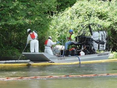
TablesEquipment and Personnel
|
|
|
Handheld Tiller
|
Surface Water
|
Removal
|
0.5-1 hour
|
Shoreline, Land
|
The hand held tiller method is applicable to narrow areas with limited access. It requires that there be little to no debris (fallen trees or submerged stumps) in the target area.
Overview The hand held tiller method is applicable to narrow areas with limited access. It requires that there be little to no debris (fallen trees or submerged stumps) in the target area. - Use a hand held, gas powered tiller to agitate the top 6 to 8-inches of the sediment
- Garden tiller with two 8-inch blades, approximately 8-inches apart
- Powered by 2-cycle gas motor
- The tiller’s engine must remain above the water surface at all times
- The tiller works best in areas with little to no bottom debris
- The tiller is best applied in non-vegetated and lightly vegetated areas. It can be used in both soft sediment and sand bed areas
- Allow the released oil to float to the surface to enable surface recovery at a collection point within the contained area. Sorbent materials will then be used for the collection and removal of recovered oil
- This strategy is an option in areas that meet one or more of the following conditions:
- Open water areas
- Areas with little to minimal debris and vegetation
- Shallow areas
- Moderate to soft bottom areas
Benefits - The unit is relatively mobile and can access hard-to- reach areas
- Prototypes were relatively light and maneuverable
Limitations - tration depth of sediment was limited to height of rake tines on tiller
- Larger units may become more difficult to handle and maneuver
- Not intended for use during weather that could interfere with floating oil removal such as rainfall.
- Physically demanding on operator in chest waders
- Limited to use in shallow water environments
- Creates a furrow by displacing sediment
- The recovery of residual oil using sediment agitation may be ineffective at recovering sinking oils, and may actually serve to facilitate downstream transport and likely dispersion.
Figures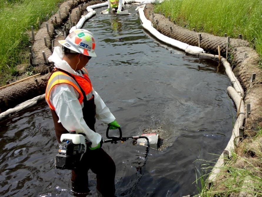
Tables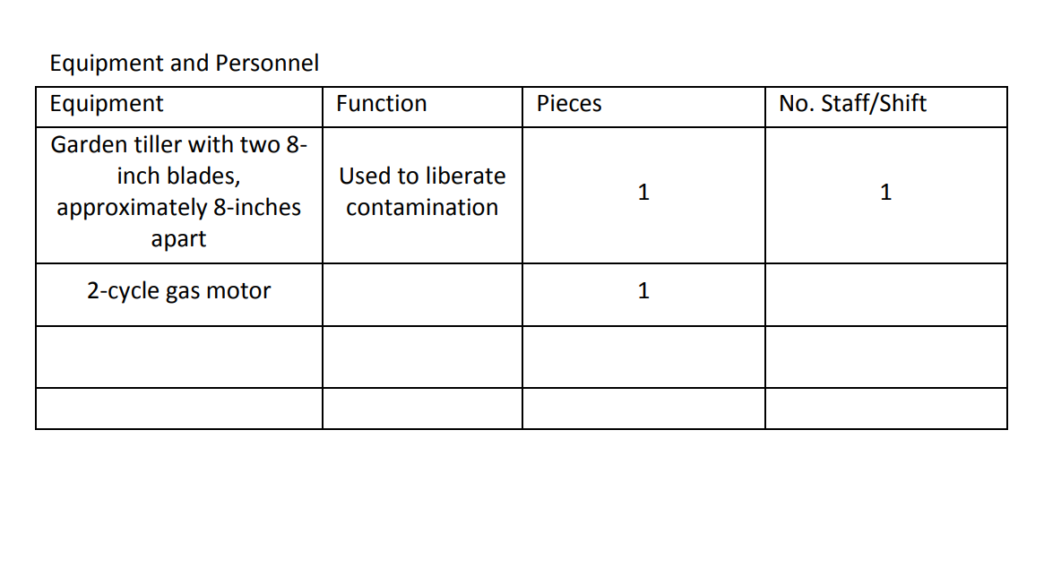
|
|
|
Hydraulic Dredger
|
Sediment
|
Removal
|
3+ hours
|
Shoreline
|
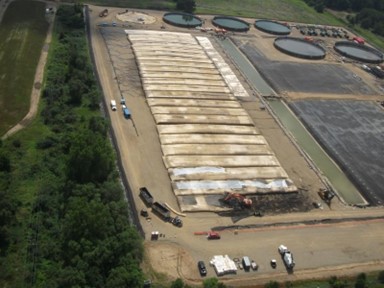
Submerged oil and oil-contaminated sediments are pumped from a dredger boat.
Overview Submerged oil and oil-contaminated sediments are pumped from a dredger boat. - In-situ submerged oil and oiled sediments are pumped via conveyance pipe into geotextile tubes for dewatering.
- A dredge pad is utilized to contain water and oil that bleeds from the geotextile tubes.
- Oil and water is collected and treated from a sump on the dredge pad.
- A viable option in areas that meet one or more of the following conditions:
- Large enough area on land for a dredge pad
- Areas where submerged oil is the removal target
- Soft bottom areas
Benefits - Reduced Hand Work
- Proven effectiveness
Limitations - Large land area required for dredge pad
- Ability to access
Figures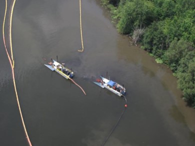
Tables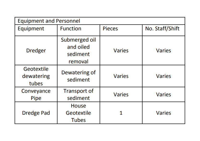
|
|
|
Marsh Buggy Mounted Spray Bar
|
Sediment
|
Containment
|
0.5-1 hour
|
River/Stream
|
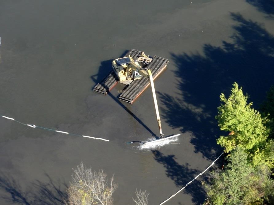
A steel tube is mounted to the arm of a marsh buggy and is connected to a pump which utilizes river water to ‘inject’ water into sediment, releasing submerged oil.
Overview A steel tube is mounted to the arm of a marsh buggy and is connected to a pump which utilizes river water to ‘inject’ water into sediment, releasing submerged oil. - 10-20 foot long stainless steel tube with deflector bar.
- 2-3 inch pump on support boat feeding water into the bar
- Uses river water pushed through a series of holes drilled into the horizontal bars.
- Sorbent materials are used for the collection and removal of recovered oil
Benefits - Less reliance on manual labor
- Able to cover large areas in short period of time
Limitations - Not very mobile
- The recovery of residual oil using sediment agitation may be ineffective at recovering sinking oils, and may actually serve to facilitate downstream transport and likely dispersion.
Figures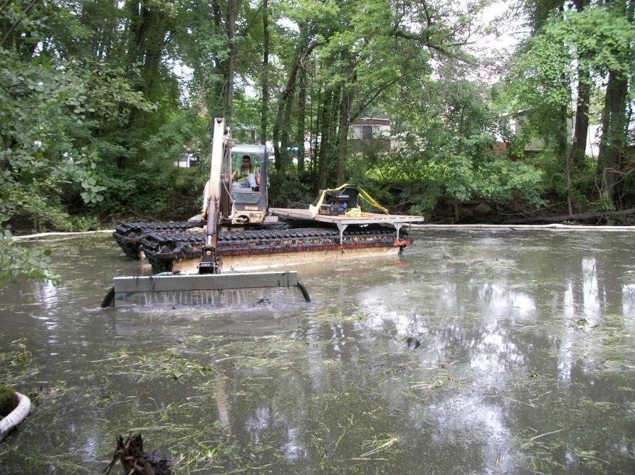
Tables
Equipment and Personnel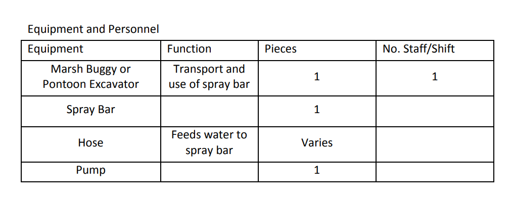
|
|
|
Mechanical Dredging
|
Surface Water
|
Removal
|
3+ hours
|
Open Water (shallow), River/Stream
|
An excavator is utilized to dig submerged oil and oil-contaminated sediments out of the impacted area.
Overview An excavator is utilized to dig submerged oil and oil-contaminated sediments out of the impacted area. - Sheet piling is utilized to isolate the targeted area.
- Pumps are utilized to remove the water within the sheet piled area.
- Dewatered sediments are mechanically excavated from the area with an excavator.
- Dredge spoils are loaded and transported to a dredge pad for further dewatering.
- A viable option in areas that meet one or more of the following conditions:
- Access for haul trucks
- Soft bottom areas for sheet piling
Benefits - Proven effectiveness
- Visibility of area to be excavated
Limitations - Access road for sediment transport
- Dewatering
- Sheet piling cannot be used in hard bottom areas
- May require hand work
Figures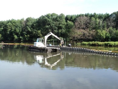
TablesEquipment and Personnel
|
|
|
Natural Attenuation
|
Surface Water
|
Removal
|
0.5-1 hour
|
Shoreline
|
Natural attenuation relies on natural processes to clean up or attenuate pollution in soil and groundwater.
(Section to be developed) Natural recovery allows the shoreline to recover without intervention. This option requires field observations of the oiling conditions and of the resources at risk to assess the effects of allowing the oil to weather naturally. In some cases, monitoring the location may be necessary to ensure that the assessment is correct. Natural recovery can be applicable on any spill incident and for any shoreline type, but requires a decision that: - To treat or clean stranded oil may cause more damage than leaving the site to recover naturally, or
- Response techniques cannot accelerate natural recovery, or
- Safety considerations could place response personnel in danger either from the oil or from environmental conditions (weather, access, etc.).
Other factors include an analysis of the resources at risk, the type and amount of oil, and the location of the site. . Natural Attenuation for Submerged Oils Benefits - Reduced disturbance to natural environment
- Cheaper than any other treatment method
- No dependence on manual labor
Limitations - Slow process
- Public perception of oil being “left behind”
Figures
TablesNone
|
|
|
Oil Recovery and Capture: Boom
|
Surface Water
|
Recovery
|
0.5-1 hour
|
Open Water (shallow), Shoreline, Culvert
|
Boom is utilized to absorb, contain, or deflect oil and sheen. Numerous configurations can be used, including the following.
Overview Boom is utilized to absorb, contain, or deflect oil and sheen. Numerous configurations can be used, including the following. - Shoreline protection – keeps oil from impacting areas of shore not already impacted
- Check mark booming
- Diversion booming
- Collection booming
Benefits - Relatively simple to use
- Effective when deployed correctly
Limitations - Waste volume
- Absorbent boom must be changed as it becomes oil and water-logged
Figures
TablesNone
|
|
|
Oil Recovery and Capture: Peat
|
Surface Water
|
Recovery
|
0.5-1 hour
|
Open Water (shallow), River/Stream, Shoreline
|
Peat and moss naturally repel water due to their chemical structure. When spread on the surface of a water body, they will float on the surface while absorbing oil. Depending upon prevailing conditions (e.g. water turbulence), peat and/or sphagnum moss can float for several days before eventually taking on water and sinking.
Overview Peat and moss naturally repel water due to their chemical structure. When spread on the surface of a water body, they will float on the surface while absorbing oil. Depending upon prevailing conditions (e.g. water turbulence), peat and/or sphagnum moss can float for several days before eventually taking on water and sinking. During this time it will absorb water-borne oil on contact. - Collection points can be established at each submerged oil location to allow for the collection of sheen and globules released by submerged oil recovery operations.
- Collection will utilize a variety of techniques including peat and/or sphagnum moss.
- Broadcast the peat over the impacted area. Allow 15-20 minutes for sheen to adhere to the peat amendment.
- Utilize air diversion (airboat or leaf blower) to mobilize the commingled peat amendment and sheen to a collection point. The collection point should be downstream or downwind depending on which is stronger at the given location.
- Utilize pool nets to recover the commingled peat amendment and sheen. The impacted debris should be taken for disposal at t6he end of each operational period
Figures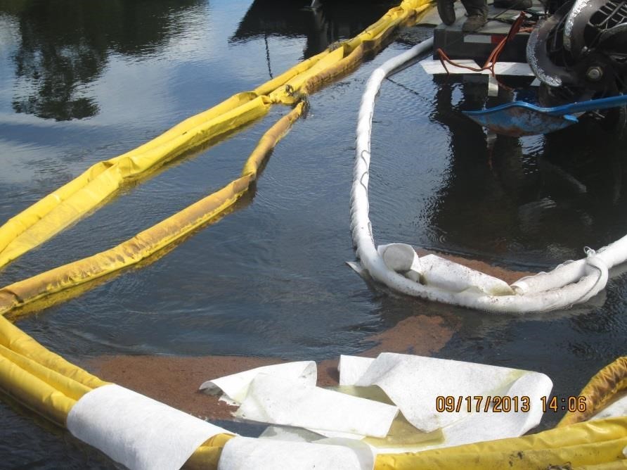
TablesNone
|
|
|
Oil Recovery and Capture: Sweep Boats
|
Surface Water
|
Recovery
|
3+ hours
|
Open Water (shallow)
|
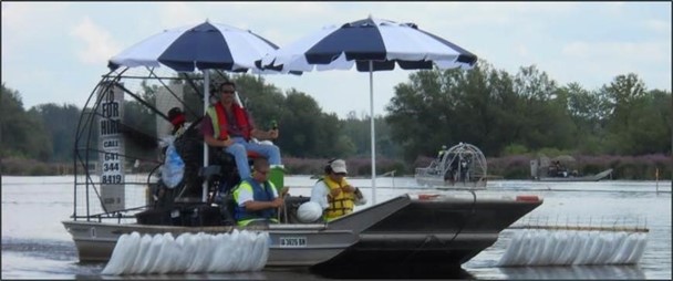
Boats are outfitted with boom and are used to capture sheen and floating oil globules as it flows downstream.
Overview Boats are outfitted with boom and are used to capture sheen and floating oil globules as it flows downstream. - Multi-Use boats
- Materials Used
- Absorbent Boom
- Sweep Boom
- Snare Boom
- Configuration
- Bow Boom
- Sweep Arms
- Tag--Along Boom
Benefits - Covers large areas quickly
Limitations - Maneuverability of boats
- Need additional containment for sheen that is not captured as it flows downstream
Figures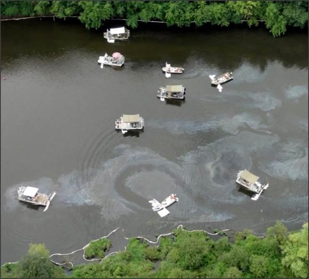
TablesNone
|
|
|
Air Sparging
|
Surface Water
|
Cleaning
|
0-0.5 hours
|
Open Water (Shallow)
|
Air sparging can be used to reduce concentrations of volatile organic compounds in water, which can appear in the event of an ethanol spill. The injection of clean air into the contaminated water enables a phase transfer of hydrocarbons from a dissolved state to a vapor phase.
Air sparging can be used to reduce concentrations of volatile organic compounds in water, which can appear in the event of an ethanol spill. The injection of clean air into the contaminated water enables a phase transfer of hydrocarbons from a dissolved state to a vapor phase. Sparging adds dissolved oxygen to the water, lessening the effect of the breakdown of compounds that may otherwise lead to hypoxic conditions. It has also been shown to be an effective remedy for soil contaminated by leaking underground storage tanks. The air sparging system can be built with parts commonly found at home centers or hardware stores. Eight coiled soaker hoses are mounted on a chain link gate with zip ties. The hoses are fitted to two four-way brass manifolds, which are in turn connected to a two-way brass manifold. This manifold is fitted to the hose of an air pump. The gate is lowered into the contaminated water. Air pumped through the sparging system aerates a small area of water for as long as it runs. Deployment Considerations and Limitations - Products such as ethanol biodegrade quickly in water, locally reducing the levels of dissolved oxygen.
- In larger volumes, ethanol and gasoline can separate in water. Responders should be aware if product is blended and prepare for gasoline containment, as well. Ethanol will mix with the water while gasoline floats.
Figures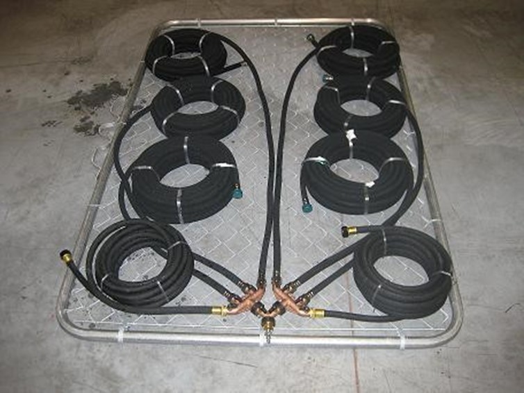
Tables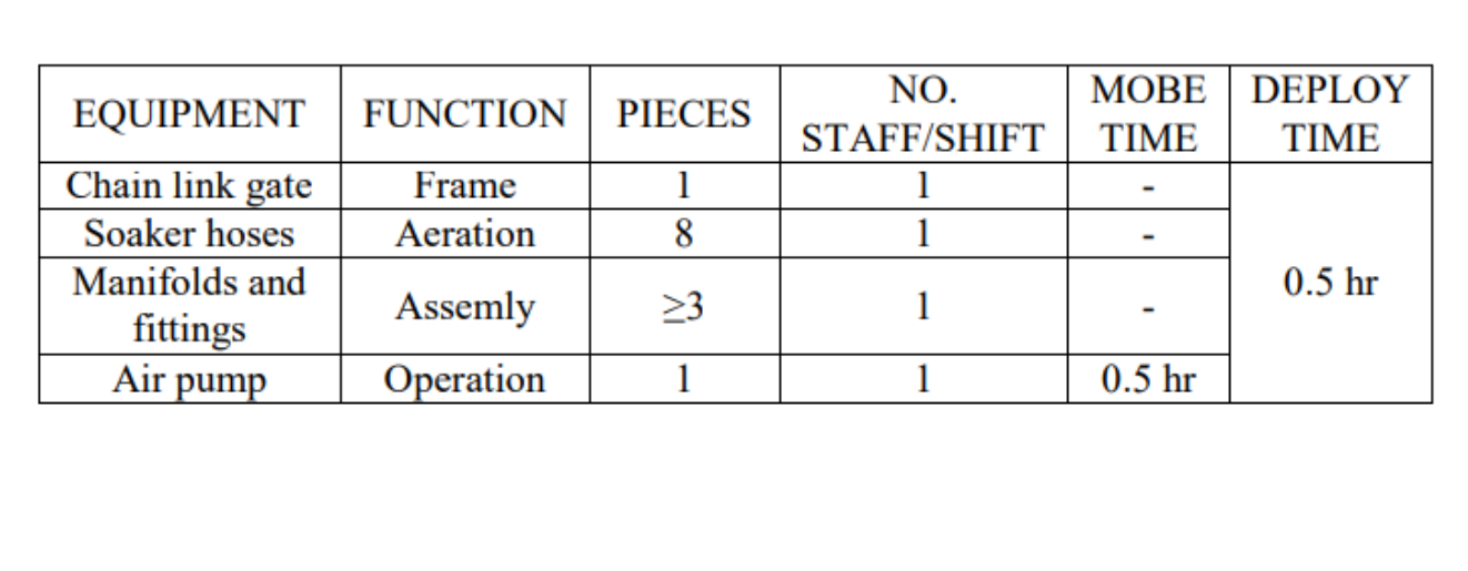
|
|
|
Hand Tool Removal and Cleaning
|
Soil
|
Removal
|
0-3 hours
|
Shoreline, Land
|
Oil or oiled sediment is picked up using gloved hands, rakes, pitchforks with screens, trowels, shovels, sorbent materials, buckets, etc.
(Section to be developed) Oil or oiled sediment is picked up using gloved hands, rakes, pitchforks with screens, trowels, shovels, sorbent materials, buckets, etc. It may include scraping or wiping with sorbent materials or sieving if the oil has come ashore as tar balls. Collected material can be placed directly into plastic bags, drums, etc., for transfer. If the containers are to be carried to a temporary storage area they should not weigh more than can be easily and safely carried by one person. This tactic can be used practically and effectively in any location or on any shoreline type or oil type where access to the shore zone is possible and safe. FiguresNoneTablesNone
|
|
|
In-Situ Burning Oily Vegetation
|
Other
|
Removal,Ignition
|
0-0.5 hours
|
Land
|
A response worker rakes oiled vegetation with a metal rake so that grass stems are oriented more or less vertically. A second response worker uses a weed burner, which consists of a flame nozzle, hosing, and a propane tank.
A response worker rakes oiled vegetation with a metal rake so that grass stems are oriented more or less vertically. A second response worker uses a weed burner, which consists of a flame nozzle, hosing, and a propane tank. The weed burner is held just above the oiled vegetation until the vegetation is burned down to stubble. Care is taken not to burn vegetation down to soil, which would damage the root system. Work is started on the upwind edge of the oiled area and proceeds downwind so that response workers are not exposed to smoke. Deployment Considerations and Limitations - Proper safety procedures must be followed, and the necessary personal protective equipment (PPE) must be used.
- Do not walk on oiled vegetation.
- Burning of oiled vegetation is conducted as a non-emergency project and has the objective of reducing re-oiling of adjacent areas. Burning proceeds downwind from its starting point. Care is taken to avoid contaminating unaffected areas. Burning is most effective immediately after the spill, before evaporation of volatile components.
- Take care to avoid secondary fires. If there is access to water, the oiled area and the surrounding vegetation can be saturated with water. Wet vegetation will still burn under the direct flame of a weed burner.
- Fire suppression must be on hand, with staff in direct control.
- Open burn permit may be required.
Figures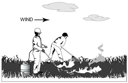
Tables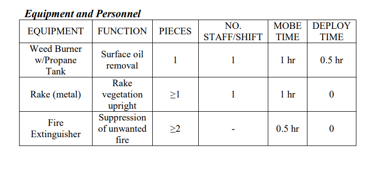
|
|
|
In-Situ Burning with Heli-Torch and Other Igniters
|
Other
|
Removal,Ignition
|
0.5-2 hours
|
Ice
|
Numerous methods are available for the ignition of floating oil. Hand-held pyrotechnic devices such as Dome igniters can be armed and tossed by hand from a helicopter or vessel.
Numerous methods are available for the ignition of floating oil. Hand-held pyrotechnic devices such as Dome igniters can be armed and tossed by hand from a helicopter or vessel. If such devices are unavailable, one can often make a simple though effective igniter on location using oil-soaked rags, sorbents, or even a roll of toilet paper. When it is unsafe to use such igniters, and particularly when a large, intense ignition area is needed, a Heli-torch may be used. An example is the Simplex Model 5400 Heli-torch. It is a helicopter-slung device for delivering measured amounts of burning gelled fuel to an oil slick for purposes of igniting the slick. The Heli-torch can be used to ignite inaccessible oil pockets collected in quiet-water areas or on melt pools on the ice. Deployment Considerations and Limitations - Proper safety procedures must be followed, and the necessary personal protective equipment (PPE) must be used.
- Follow all manufacturer’s instructions carefully. Designated personnel on the surface and in the air maintain a constant watch of the fire and smoke plume, the condition of the boom, the speed and positions of the towing vessels, and the proximity of the burn operations to other vessels, oils slicks, the shoreline, etc. In addition, each vessel should maintain constant contact with the supervisor. The supervisor of the burn operation must be in direct radio contact with all elements of the burn team, including aircraft and the mixing/loading crew.
- It is critical that communications be available to ensure coordination between the burn operations supervisor and all elements of the response. All personnel involved in the operation must be in constant contact with the burn operations supervisor. The following communications are necessary for a burn on water:
- Dedicated radio links and equipment with specific frequencies for air-to-air and air-to ground communications
- Dedicated radio links and equipment with specific frequencies for vessel-to-vessel and vessel to- command communications
- Repeater stations as appropriate for distant or blocked communications paths
- Emergency manual signal (e.g., light or siren)
- Take care when filling, mixing, and dispensing raw or gelled fuel. Always connect a ground wire to an earth ground. Use a non-sparking pump in a well-vented area. When mixing by hand, use wooden or aluminum paddles. Have at least two 20- lb dry-chemical fire extinguishers in both the fuel mixing and Heli-torch filling areas. Personnel mixing and dispensing fuel must wear antistatic protective clothing.
- The charter company supplying the helicopter must be FAA- certified to sling-load petroleum. In addition, the pilot must have FAR Part 137 certification.
- Burning gelled fuel may sometimes fall off the Heli-torch while in transit to or from the burn site. Pilots should plan their flight path to minimize the risk of starting unwanted fires.
- Cerntain environmental limitations restrict the feasibility of in- situ burning. Optimal environmental conditions are:
- Winds less than 20kt
- Waves less than 2 to 3 ft
- Currents less than ¾ kt relative velocity between boom and water
- The following oil thicknesses are required to support combustion:
- 2 to 3 mm for fresh crude oil
- 3 to 5 mm for diesel and weathered crude
- 5 to 10 mm for emulsions and Bunker C
- Emulsification can affect ignitability. Most oils are readily combustible if water content is less than 25%. For water contents greater than 25% it may be necessary to apply an emulsion breaker to obtain ignition.
Figures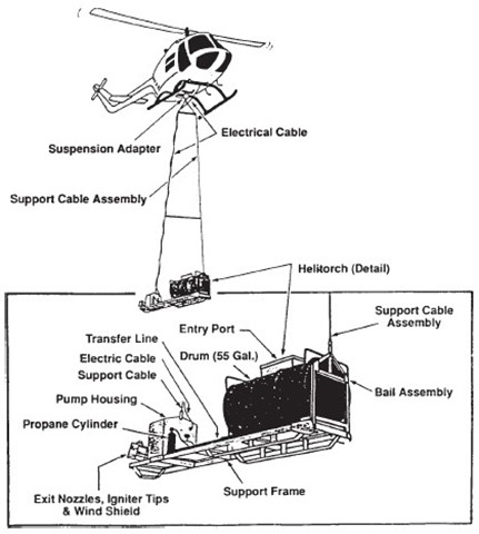
Tables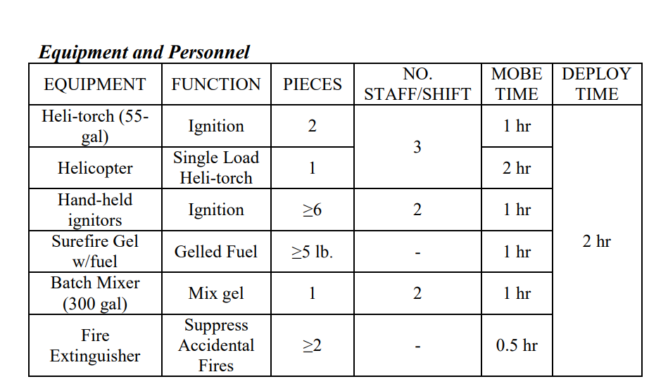
|
|
|
Phytoremediation
|
Soil
|
Removal
|
3+ hours
|
All
|
Naturally occurring microorganisms use oxygen to convert hydrocarbons into water and carbon dioxide. This process usually occurs at the water interface and is limited by oxygen and nutrient availability and by the exposed surface area of the oil.
Naturally occurring microorganisms use oxygen to convert hydrocarbons into water and carbon dioxide. This process usually occurs at the water interface and is limited by oxygen and nutrient availability and by the exposed surface area of the oil. If these factors can be increased, the rate of biodegradation can be accelerated. FiguresNoneTablesNone
|
|
|
Pumper (Flush) Boat
|
Sediment
|
Removal,Recovery
|
0.5-1 hour
|
River/Stream
|
A pumper boat has mounted steel pipes connected to a pump, which utilizes river water to ‘inject’ water into sediment, releasing submerged oil.
|
|
|
Raking
|
Surface Water
|
Removal
|
0.5-1 hour
|
Open Water (shallow)
|
A hand held rake is used to agitate sediment, releasing submerged oil. The rake is best used in non- and lightly vegetated areas in shallow water.
Overview A hand held rake is used to agitate sediment, releasing submerged oil. The rake is best used in non- and lightly vegetated areas in shallow water. - Use a hand held rake to agitate the sediment to release submerged oil
- The rake is a steel tine garden rake with a three inch depth penetration
- Sorbent materials are used for the collection and removal of recovered oil
Benefits - A rake is very mobile and can access shallow areas
- Simple tool not requiring an engine
Limitations - Physically demanding on operator in chest waders (requires bending and repetitive motion)
- Inconsistent application of force
- Time consuming
- Penetration depth of creek sediment is limited to height of rake tines
- Limited to use in shallow water environments
- The recovery of residual oil using sediment agitation may be ineffective at recovering sinking oils, and may actually serve to facilitate downstream transport and likely dispersion.
Figures Tables
|
|
|
Reinforced Pipe Drag
|
Sediment
|
Removal
|
0.5-1 hour
|
River/Stream
|
The reinforced pipe drag is a 10-foot-long by 5-foot-wide rectangular welded aluminum structure covered with containment cloth. It is connected to a boat-mounted trash pump, which uses river water pushed through a series of holes drilled into the horizontal bars to “inject” water into the sediment, releasing trapped oil.
Overview The reinforced pipe drag is a 10-foot-long by 5-foot-wide rectangular welded aluminum structure covered with containment cloth. It is connected to a boat-mounted trash pump, which uses river water pushed through a series of holes drilled into the horizontal bars to “inject” water into the sediment, releasing trapped oil. - Oil absorbent snares (pom-poms) attached on bottom
- Pulled horizontally over the sediment using a land-based capstan motor/pulley anchored to a tree.
- The bottom drag works best in open water areas or areas with minimal vegetation and without submerged debris. It is best used in larger areas with moderate water depths.
- Additional sorbent materials are used for the collection and removal of recovered oil
Benefits - Covers a moderately sized area with each pass of the device over the sediment
Limitations - Difficult to maneuver
- Not effective in areas with much vegetation or submerged debris
- The recovery of residual oil using sediment agitation may be ineffective at recovering sinking oils, and may actually serve to facilitate downstream transport and likely dispersion.
Figures Tables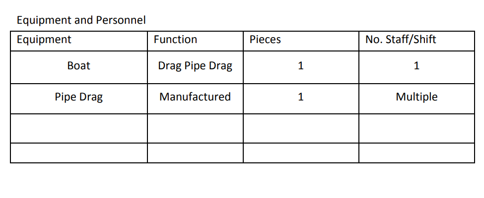
|
|
|
Rotating Stinger
|
Sediment
|
Containment
|
0.5-1 hour
|
River/Stream
|
A rotating stinger consists of a hand-held discharge wand connected to a boat-mounted pump, which utilizes river water to ‘inject’ water into sediment, releasing submerged oil. Uses river water which is released from a series of holes drilled into the horizontal pipes.
Overview A rotating stinger consists of a hand-held discharge wand connected to a boat-mounted pump, which utilizes river water to ‘inject’ water into sediment, releasing submerged oil. Uses river water which is released from a series of holes drilled into the horizontal pipes - A set of stingers consists of hand held discharge wands equipped with water supply
- The rotating stinger device is constructed using an 8-foot long, 1 ½- inch diameter steel vertical pole with two 6-foot long horizontal steel pipes attached approximately 1-foot from the bottom at 90- degrees to the vertical pole and 180-degrees from each other
- The drilled holes are angled toward the bottom where it will agitate and release submerged oil from the sediment.
- Uses high volume/low pressure supplied by a submersible, trash or water pump (3-5 psi)
- Recommended for large non-vegetated areas with sand or hard river bottoms and shallow or moderate water depths
- Works best in areas with submerged oil limited to the upper couple of inches of sediment. Spreading the flow across 12 feet of pipe through several small holes increases energy losses, which reduces the effective force of the water jets and limits the depth of penetration into the sediment.
- Sorbent materials are used for the collection and removal of recovered oil
Benefits - The single nozzle is much more forceful than the rotating stingers
- Relatively mobile
Limitations - Trash pump intake may suck in debris and mulch, clogging discharge holes on horizontal stingers
- The prototype stinger was cumbersome in vegetated areas
- The stinger device as described here could not be rotated due to vegetation, which limited the areas in which it could be used effectively
- Physically demanding for operator
- The recovery of residual oil using sediment agitation may be ineffective at recovering sinking oils, and may actually serve to facilitate downstream transport and likely dispersion.
Figures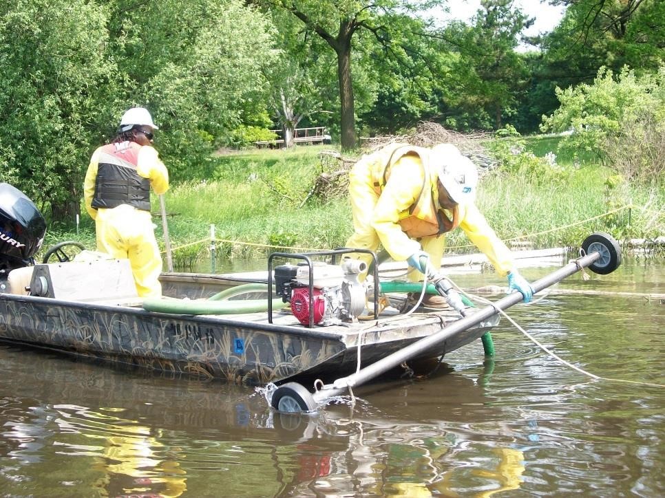 Tables
|
|
|
Vacuum removal
|
Soil
|
Removal
|
0.5-1 hour
|
Land
|
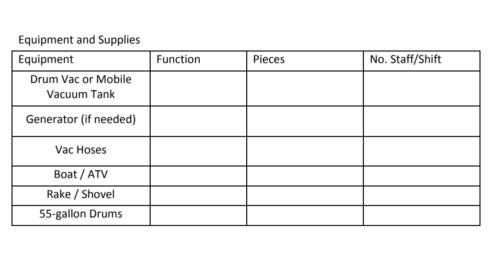
The portable vacuum consists of a 15-inch-long by 3-inch-wide head attached to a vacuum hose. Debris collected from the vacuum is sucked through 2-inch-diameter flexible hose and deposited in a 55-gallon drum.
Overview - The portable vacuum consists of a 15-inch-long by 3-inch-wide head attached to a vacuum hose. Debris collected from the vacuum is sucked through 2-inch-diameter flexible hose and deposited in a 55-gallon drum
- Vegetation should be cleared from area prior to work
- Devices can be transported by boat or ATV
- Effective when the area is previously hand raked and residual loose material can be vacuumed up. May also be used in naturally dry loose material.
- Option in areas that meet one or more of the following conditions:
- Areas where contaminated soil has been raked and residual material can be vacuum-removed
- Areas with little vegetation
- Areas where tar balls and/or patties are the removal target
- relatively dry areas or areas with granular, loose soils
 Benefits - Effective on loose, dry, granular soils
- Removes loose tar balls and patties from soil
- The unit is relatively mobile and can be deployed to hard-to-reach areas
Limitations - Not appropriate for removing tar and contaminated soil attached to roots and vegetation
- Effective distance of vacuum is limited
- Wet and/or cohesive soils will clog the vacuum head and hose
 FiguresTables
|
|
|
Vessel Mounted Bottom Drag
|
Sediment
|
Removal
|
3+ hours
|
River/Stream
|
The vessel mounted bottom drag device consists of an 8-foot long (2-inch diameter) steel horizontal tube with wheels attached on both ends, and is connected to a boat-mounted trash pump, which uses river water pushed through a series of holes drilled into the horizontal bars to “inject” water into the sediment, releasing trapped oil.
Pipe Drag The vessel mounted bottom drag device consists of an 8-foot long (2- inch diameter) steel horizontal tube with wheels attached on both ends, and is connected to a boat-mounted trash pump, which uses river water pushed through a series of holes drilled into the horizontal bars to “inject” water into the sediment, releasing trapped oil. - The bottom drag discharges water through holes in the steel pipe
- The device is lowered to the sediment surface and then pulled horizontally over the sediment
- The bottom drag works best in open water areas or areas with minimal vegetation and without submerged debris. It is best used in larger areas with moderate water depths
- Sorbent materials are used for the collection and removal of recovered oil
Benefits - Covered a fairly large area with each pass of the device over/through the sediment
- Relatively mobile, manageable equipment
Limitations - Multiple passes through an area are required for complete coverage
- Submerged debris (fallen trees, logs or stumps) will interfere with proper operation of the device
- Although the unit described here has wheels, it does not roll over sediment as designed, but cuts into the sediment.
- The recovery of residual oil using sediment agitation may be ineffective at recovering sinking oils, and may actually serve to facilitate downstream transport and likely dispersion.
Figures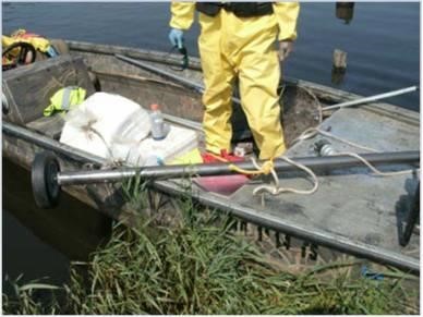 TablesNone
|
|
|
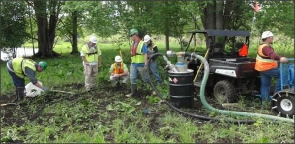
Water Flushing Pipe Drag
|
Sediment
|
Removal
|
0.5-1 hour
|
River/Stream
|
The vessel mounted bottom drag device consists of an 8-foot long (2-inch diameter) steel horizontal tube with wheels attached on both ends, and is connected to a boat-mounted trash pump, which uses river water pushed through a series of holes drilled into the horizontal bars to “inject” water into the sediment, releasing trapped oil.
Overview - 3 horizontal 4-foot-long, 1-inch diameter steel pipes on two 3-foot- long parallel bars with steel skids.
- Injects river water through a series of holes drilled into the horizontal bars.
- Pulled horizontally over the sediment using a land-based capstan motor/pulley anchored to a tree
Benefits - Relatively mobile, manageable equipment.
- Covers a moderately sized area with each pass of the device over the sediment.
Limitations - Multiple passes through an area are required for complete coverage
- Submerged debris (fallen trees, logs or stumps) will prevent operation of device as designed
- Requires 4 to 5 operators to submerge and pull the device along river bottom
- The recovery of residual oil using sediment agitation may be ineffective at recovering sinking oils, and may actually serve to facilitate downstream transport and likely dispersion.
Figures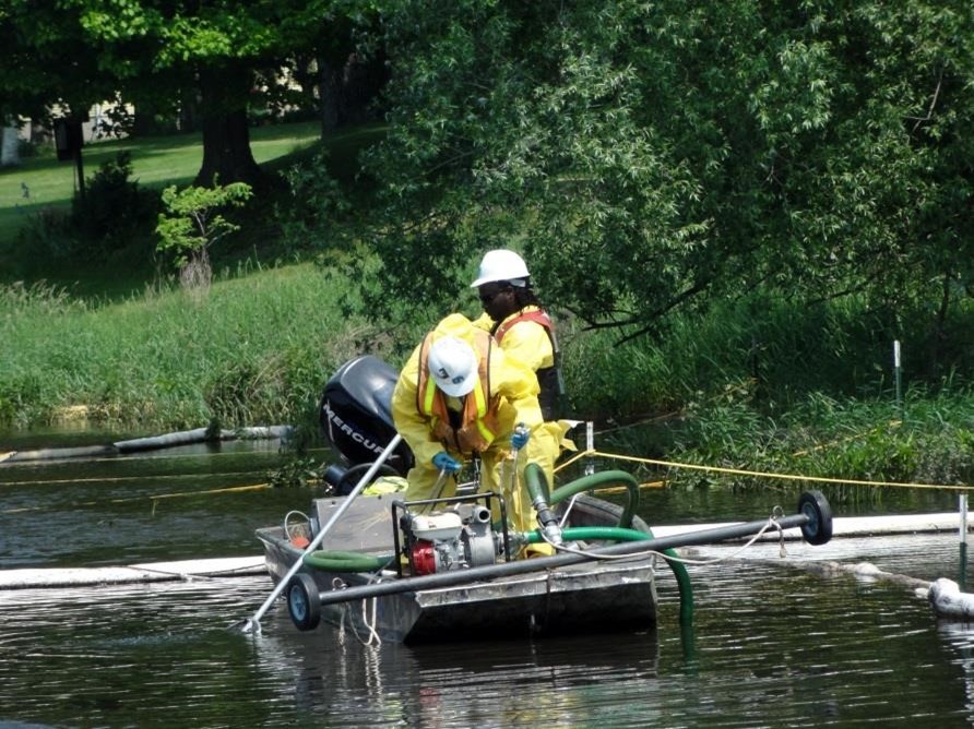 Tables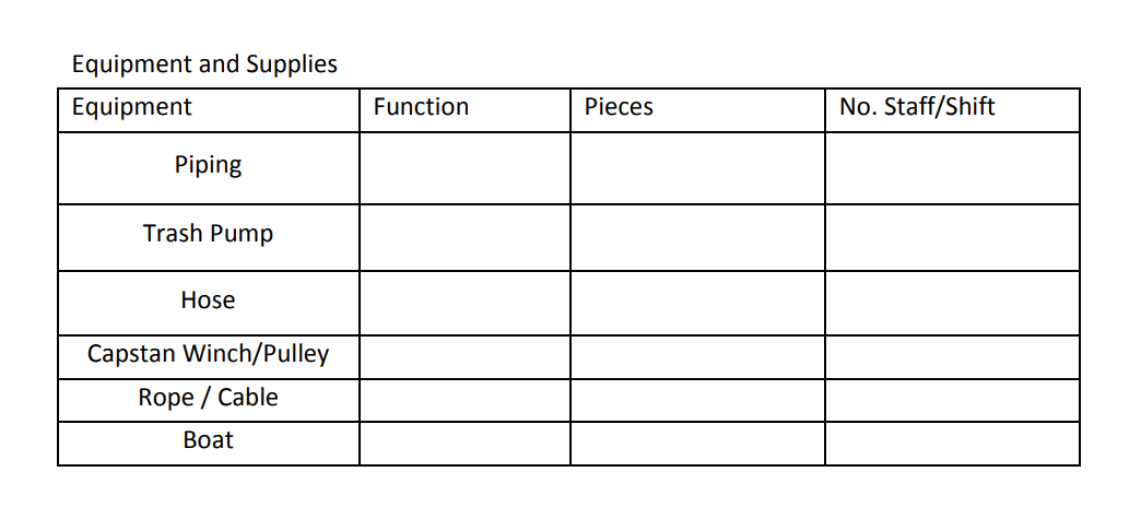
|
|
|
Winter Excavation
|
Soil
|
Excavation
|
3+ hours
|
Land
|
Utilizes a variety of tools, equipment and methods to remove oil and oil-contaminated sediment and soil while materials are frozen or near�frozen during the winter months.
Overview Utilizes a variety of tools, equipment and methods to remove oil and oil-contaminated sediment and soil while materials are frozen or near- frozen during the winter months. - Methods of Removal
- Complete Solidification
- Entire area and depth frozen before Removal execution
- Consecutive Lifts
- Solidification and Removal of Material in lifts
- Excavation Delineation
- Haul Out on Access Road
- Tools/equipment
- Low Pressure Ground Equipment
- Wide pads, lighter weight
- Bombadier
- Tracked Dump Truck
- Dozers
- Small Excavators
- Pumps
- Isolation Materials
- Silt Fence, Portable Dams
- Methods of Solidification
- Remove insulating material (leaves, etc.)
- Freeze by exposure
- Vibration increases Thermal Transfer (Principle of Thermal Dynamics)
- Liquid to surface
- Restoration
- Low Ground Pressure Equipment
- Vegetation sub-structure remains in place
- Replacement of Native seed bed
- Erosion control devices will remain in place until vegetation has been re-established
Benefits - Minimizes impact to the area
- Liquid materials solidify for controlled removal Allows for continuation of clean up at large sites during winter months
Figures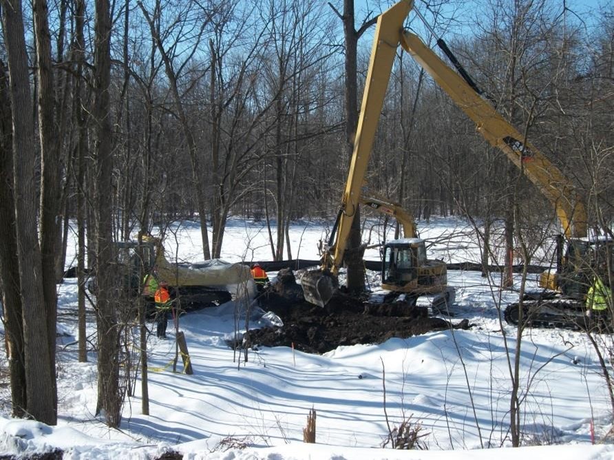 TablesNone
|
|
|
Woody Debris Removal
|
Surface Water
|
Disposal
|
3+ hours
|
Open Water (Deep)
|
Heavy equipment is utilized to remove submerged debris, releasing trapped oil and preparing sediment for submerged oil treatment methods such as chain drag
Overview Heavy equipment is utilized to remove submerged debris, releasing trapped oil and preparing sediment for submerged oil treatment methods such as chain drag, which cannot be performed in areas with significant quantities of submerged debris. - Can be done using Marsh Buggy or Pontoon Excavator
- Utilizes thumb attachment on excavator
- Debris is loaded onto barges or cargo boats which then transport the debris for disposal
Benefits - Reduced Hand Work
- Larger lifts, material more intact
- Can be done in deeper waters than manual extraction could
- Opens area for work to begin
Limitations - Impact to area
- Ability to access
Figures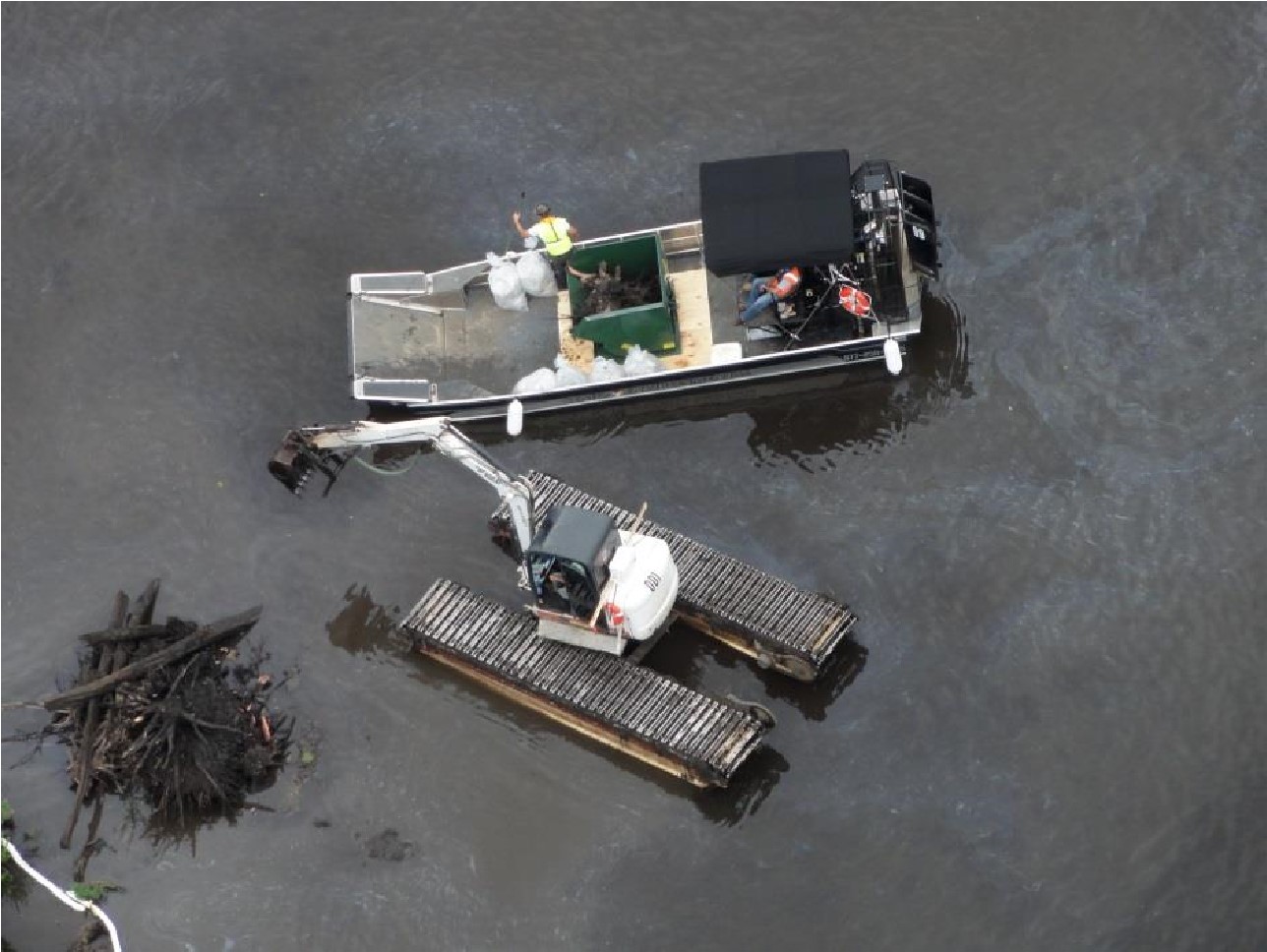 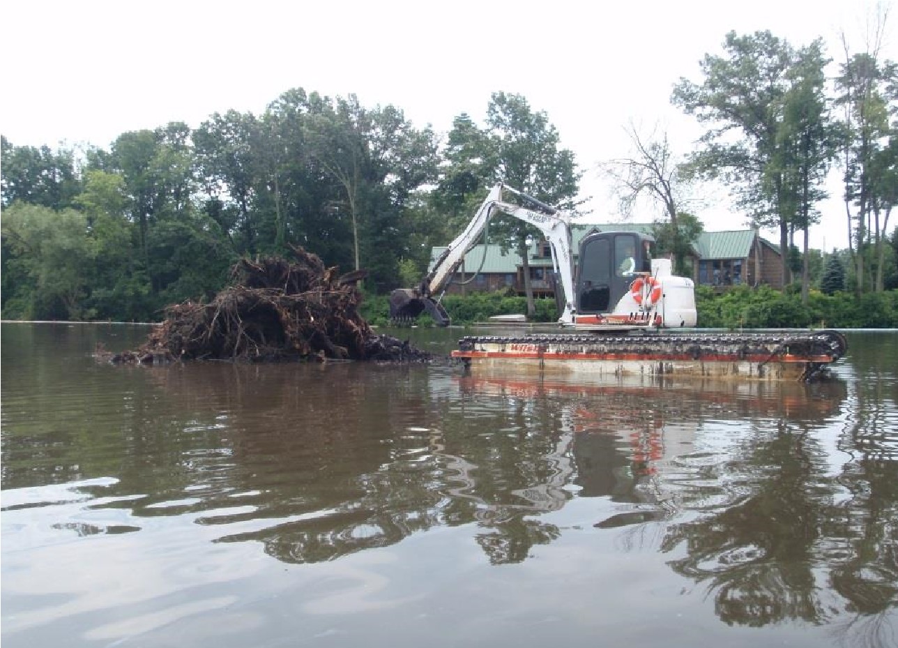 Tables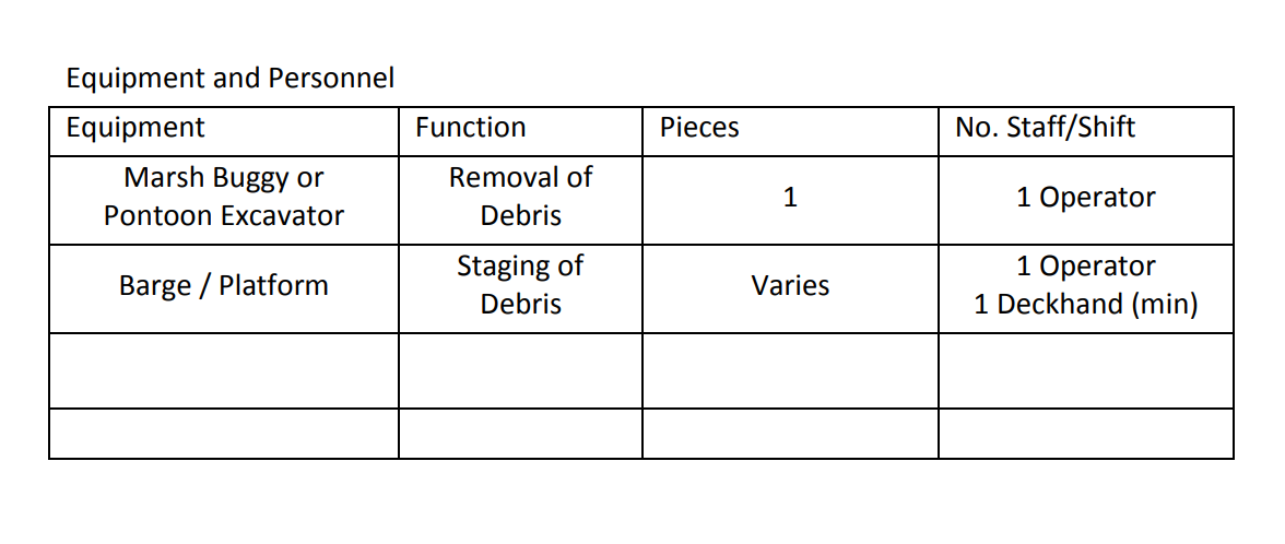
|
|
|
Collection and Removal of Debris/Vegetation
|
Surface Water
|
Collection
|
1 hour
|
Open Water (Shallow)
|
Debris can be removed from the path of a spill to prevent oiling, or after oiling to accommodate cleanup or ensure the safety of responders. Manual and mechanical methods can be used, depending on the type, size, and amount of debris.
(Section to be developed) Debris can be removed from the path of a spill to prevent oiling, or after oiling to accommodate cleanup or ensure the safety of responders. Manual and mechanical methods can be used, depending on the type, size, and amount of debris. In fast water, two barriers can be deployed in parallel. The first barrier retains debris only, the second barrier retains oil in the calm area between the barriers. Foam filled boom is recommended. Upstream barriers that allow water and oil passage but retain debris, such as snow fence, chain link fencing, or chicken wire, can be use with floatation or ballast to improve efficacy.
Oiled vegetation or oil trapped in vegetation can be removed to prevent the oiling of wildlife or secondary oil releases. Oiled vegetation is cut with weed trimmers, blades, etc., and picked or raked up and bagged for disposal.
Vegetation removal is useful when the risk of secondary release or contaminating wildlife is greater than the value of the vegetation to be cut, and there is no less destructive method available. Removal operations should be monitored to minimize the degree of root destruction and mixing of oil into sediments. FiguresNoneTablesNone
|
|
|
Collection and Removal of Sediment
|
Sediment
|
Collection
|
3+ hours
|
Land
|
Mechanical removal is more rapid than manual removal, but generated larger amounts of waste.
(Section to be developed) Mechanical removal is more rapid than manual removal, but generated larger amounts of waste. The method of operation varies considerably, depending on the type of equipment that is available and the ability of that equipment to operate at the site.
Some equipment (e.g. Bobcats, backhoes, loaders, or vacuum trucks) can remove and transfer material directly to a truck or temporary storage area. Other types (e.g. graders and bulldozers) are less efficient and require two steps to move or cast material that must then be picked up by other equipment for transfer. FiguresNoneTablesNone
|
|
|
Collection from Pit or Trench
|
Soil
|
Collection
|
3+ hours
|
Culvert
|
An excavated trench is used to intercept the flow of a spill or divert the flow around a sensitive area. Dig the trench at right angles to the flow of the spill.
An excavated trench is used to intercept the flow of a spill or divert the flow around a sensitive area. Dig the trench at right angles to the flow of the spill. The trench should be angled slightly downslope to avoid excessive pooling in the trench.
Place excavated material on the downhill side of the trench. In areas with a low water table line the sides and bottom of the trench with plastic sheeting or similar impermeable materials. Where the groundwater table is high, line the downhill side of the trench.
The trench can be flooded with water to inhibit spill penetration into sediments and to stimulate flow toward the recovery device in the trench or pit.
Deployment Considerations and Limitations
- Disposal of construction material should be taken into account before using this tactic
- Do no excavate an interception trench in an area where the excavation will cause more damage than the spill itself.
- On pads check for buried pipe and/or cables prior to excavation. Obtain a civil work permit from the operator.
- The amount of oil will be estimated based on gauging by appropriate means (e.g., Coliwasa tube). Emulsion samples will be collected and analyzed for oil content.
Figures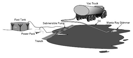
Tables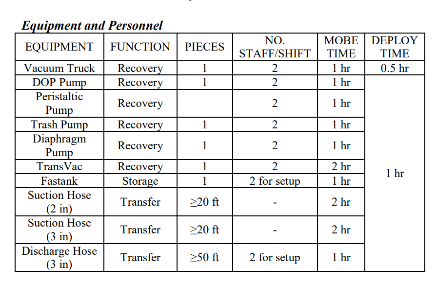
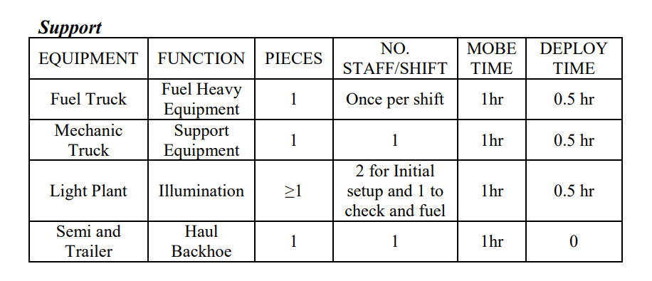
|